
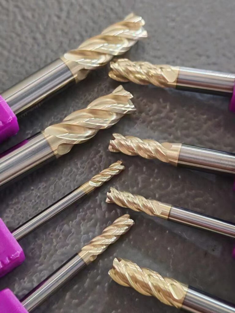
Tungsten Carbide End Mill
Engineered from tungsten carbide, they offer exceptional cutting efficiency and edge retention. Optimizing CNC machining processes, these inserts maintain consistent performance across diverse metal – working applications.
Products Provided by Kedel
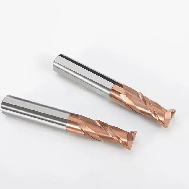
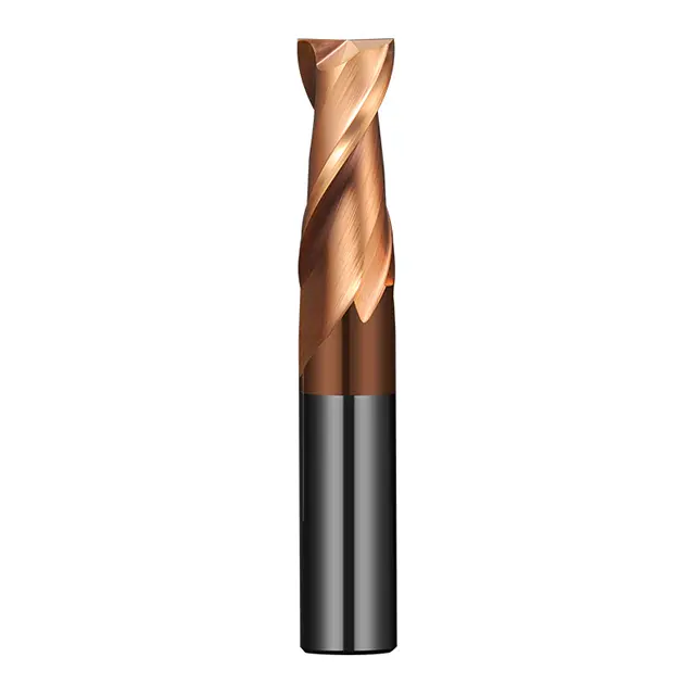
Flat - End Mill
Ball - Nose End Mill
Corner - Radius End Mill
Tapered End Mill
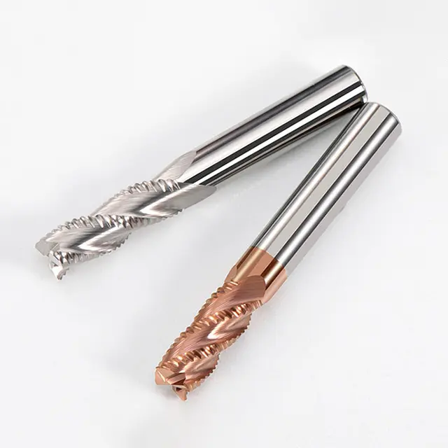
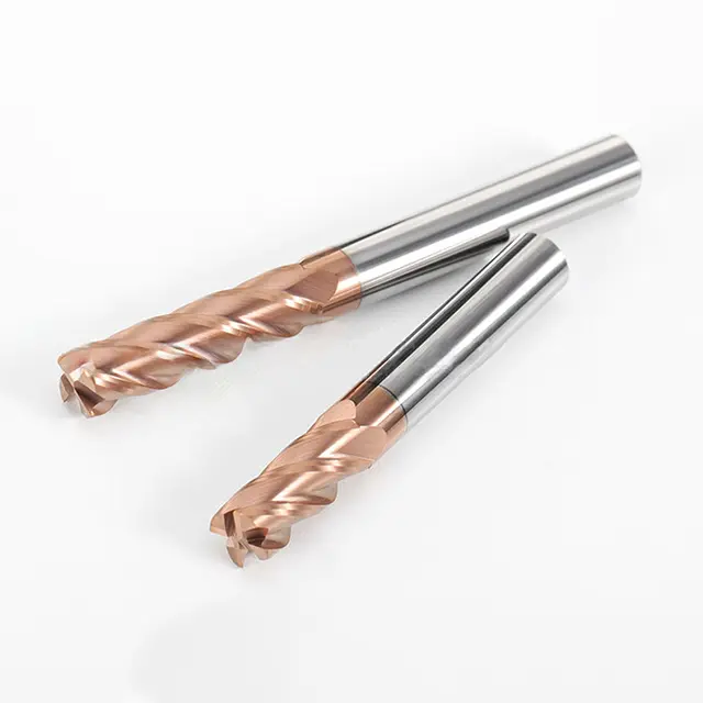
Roughing End Mill
Keyway End Mill
Click the image to view product details
Need custom blades? We design and make them
Application Scenarios
Processing different materials enables the manufacturing of diverse products across industries, meeting specific functional, performance, and application needs while driving technological innovation and industrial development.
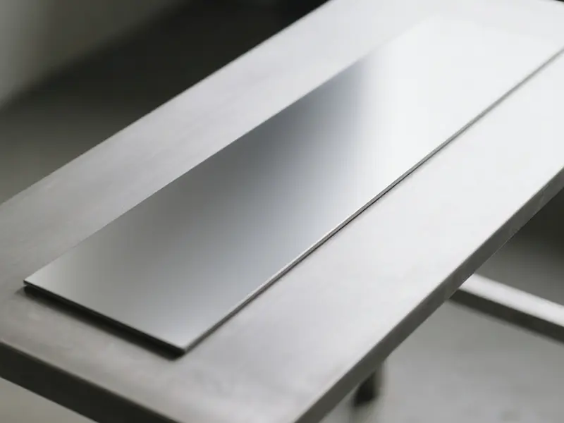
Ferrous Metals
Non – Ferrous Metals
High – Temperature Alloys and Difficult – to – Machine Alloys
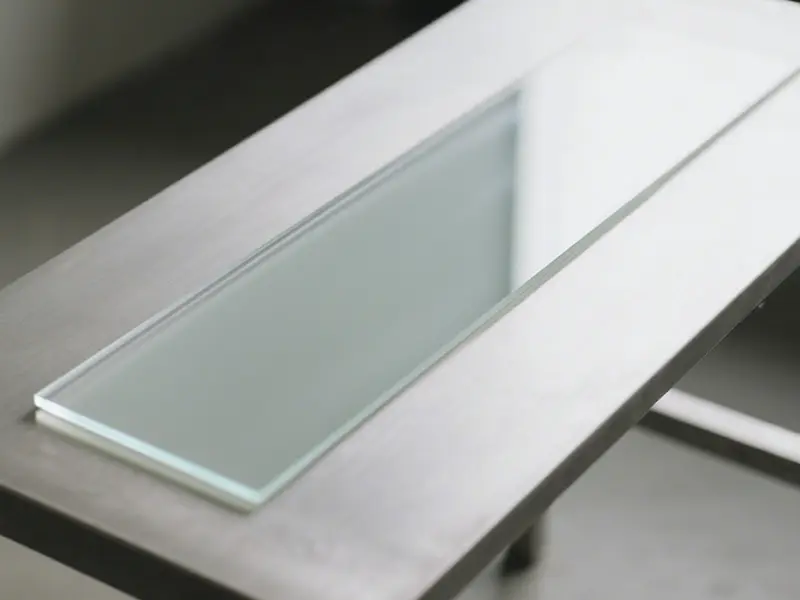
Plastics and Composite Materials
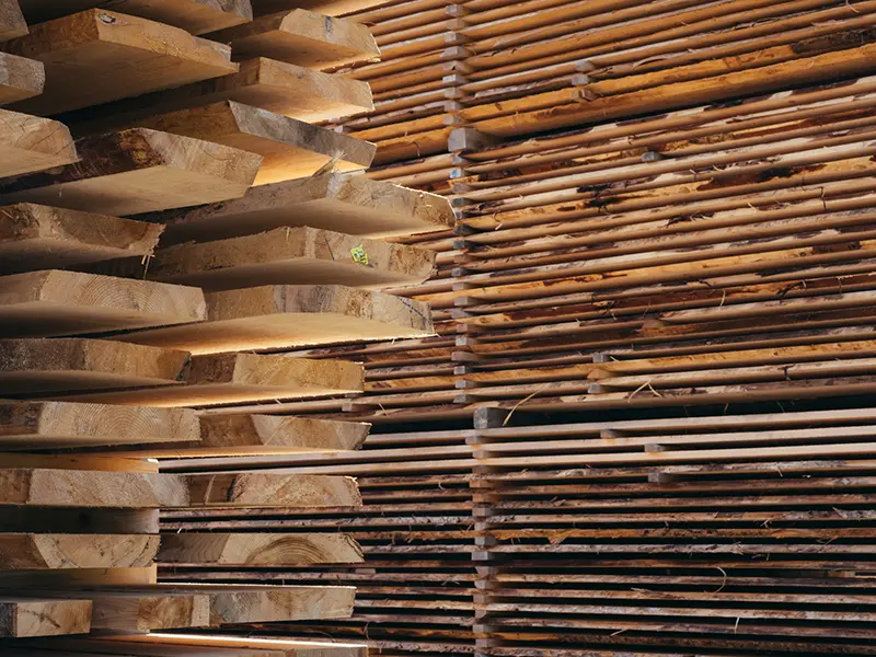
Wood and Plates
Uncover Your Needs with Us!
The smoothness and parallelism of the end mill shank, as well as the edge geometry, flute shape, helix angle and hardness of the end mill cutting part are all closely related to the milling effect. Please inform us of your or your customers’ specific milling requirements, and provide relevant drawings or samples. We will carry out customized production accordingly.
What is a Tungsten Carbide end Mill ?
A vertical end mill is a professional cutting tool in CNC machining that works through high – speed rotational cutting, capable of processing various materials including metals, plastics, composites, and wood – based materials. By means of the rotating cutting edges on its cylindrical surface and end face, it enables efficient machining of planes, grooves, steps, and complex contours. Classified by edge shape , material , and structure, it structurally consists of a shank, a cutter body, and cutting edges made of hard materials, featuring high precision, strong rigidity, versatile applicability, and effective chip evacuation. Widely used in industries such as mold manufacturing, automotive parts processing, aerospace component machining, general machinery, and electronic device fabrication, it serves as a core tool in CNC machining production lines, ensuring machining accuracy, surface quality, and production efficiency.
What are the common tool types used in Tungsten Carbide end Mill ?
Different types of end mills, through structurally differentiated designs, are respectively adapted to machining scenarios such as flat surfaces and steps, curved contours, angled draft surfaces, high-efficiency roughing, and precision keyways, satisfying the core requirements of shape, precision, and efficiency.
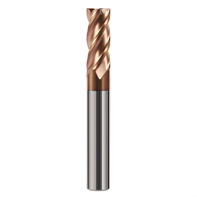
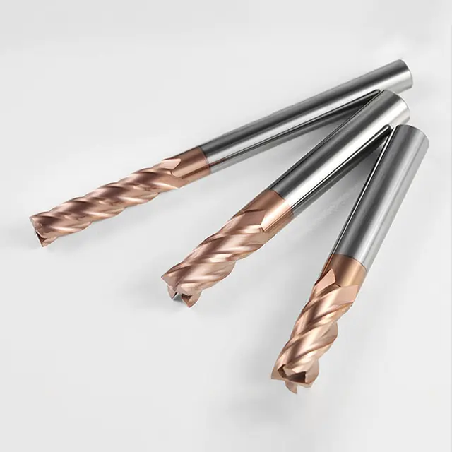
Flat - End Mill
Structural Features: Has flat cutting edges on both the end face and side walls, with a right – angle (or small chamfer) tip. Equipped with straight or helical flutes for chip removal.
Functional Advantages: Allows side – edge milling for flat surfaces and steps, and end – edge milling for shallow grooves. It has high cutting edge strength, suitable for heavy feed rates in planar machining.
Typical Applications: Machining flat surfaces of molds, step features of mechanical parts, and general – purpose milling of metals and non – metals.
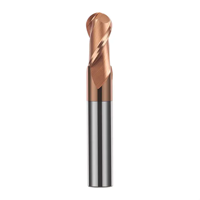
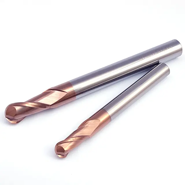
Ball - Nose End Mill
Structural Features: Features a spherical tip (circular arc cutting edge) with a smooth arc transition on the side walls. Designed with helical flutes.
Functional Advantages: The arc edge reduces machining marks, making it ideal for 3D contour machining. The smooth edge transition avoids scratch marks on workpieces.
Typical Applications: Machining curved mold cavities (such as injection molds), aerospace impellers, and complex contoured parts.
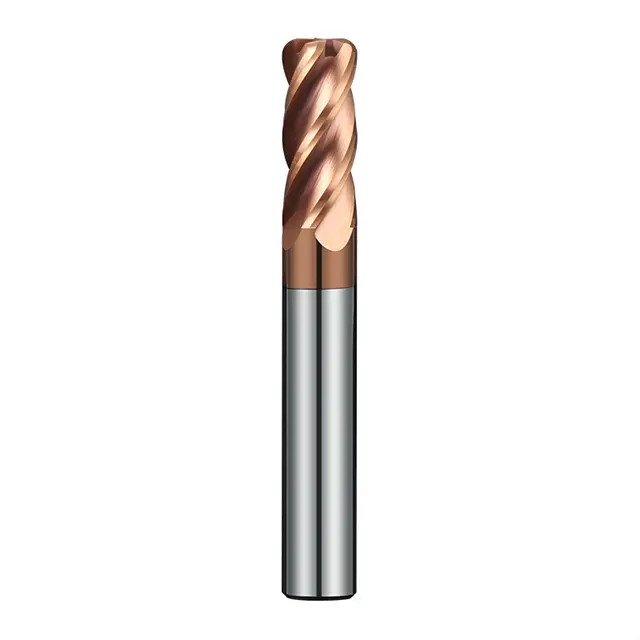
Corner - Radius End Mill
Structural Features: Has a small rounded corner (radius r) at the tip, combining the characteristics of flat – end and ball – nose mills.
Functional Advantages: The rounded edge distributes cutting forces, reducing tip wear. It balances planar and contour machining and has high chipping resistance.
Typical Applications: Chamfering on molds, contouring of automotive parts (like wheel hubs), and semi – finish/finish machining of hardened steel.
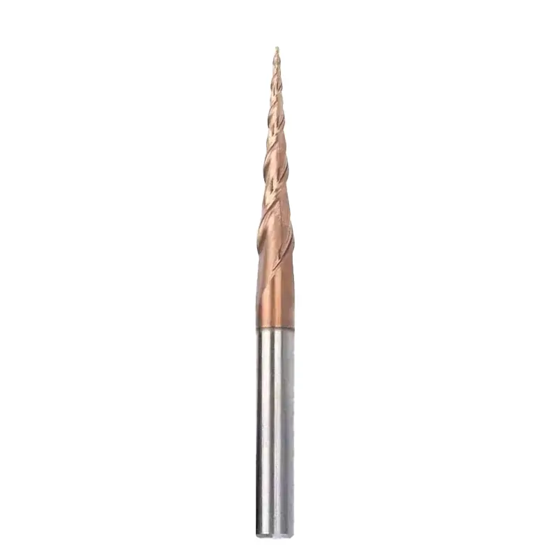
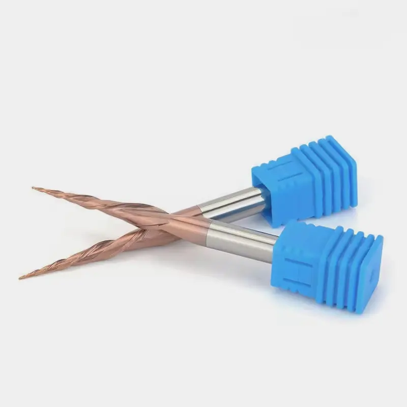
Tapered End Mill
Structural Features: Has a tapered shank (e.g., 3°–5° taper angle), and the cutting edges follow the taper. The tip may have a radius or a flat end.
Functional Advantages: Can machine tapered surfaces in a single pass, eliminating the need for multi – step programming. It is optimized for slant contour machining.
Typical Applications: Machining draft angles on molds, slanted surfaces on aerospace structures, and angular profiling in woodworking.
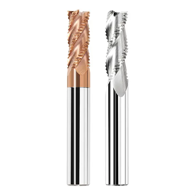
Roughing End Mill
Structural Features: Has dense, serrated cutting edges (resembling corn rows), a large helix angle, and deep chip grooves.
Functional Advantages: Multiple teeth cut simultaneously, enabling high – depth and high – width roughing with efficient chip breaking. It maximizes material removal rates.
Typical Applications: Rough stock removal on mold steel, coarse milling of cast blanks, and heavy – duty machining of non – ferrous metals.
Keyway End Mill
Structural Features: Designed with 2 flutes, end cutting edges that extend through the center (allowing axial feeding), and straight or short – helical flutes.
Functional Advantages: Has strong axial cutting capability (similar to a combination of an end mill and a drill), ensuring high – precision keyway machining with symmetric side edges.
Typical Applications: Machining keyways on mechanical shafts, positioning grooves in molds, and high – precision narrow slotting.
What are the common working methods?
End mills with different working methods adapt to various machining scenarios such as rough/finish machining, planar/side/deep groove processing through cutting directions, edge utilization, and feeding methods, aiming to meet the core requirements of machining accuracy, efficiency, and workpiece characteristics.
Climb Milling
- Principle: The cutter’s rotation direction aligns with the feed direction, so cutting forces press the workpiece against the table, minimizing vibration.
- Scenario: Finish machining of steel, cast iron, etc., where a smooth surface (low roughness) is required.
- Advantage: Stable cutting, reduced workpiece vibration, superior surface finish, and slower tool wear.
Conventional Milling
- Principle: The cutter’s rotation direction opposes the feed direction; cutting starts from pre-machined surfaces, generating an upward lifting force on the workpiece.
- Scenario: Roughing operations (e.g., machining castings with hard scales, or weakly clamped workpieces).
- Advantage: High impact resistance, suitable for rough blanks; lower requirement for tool impact toughness.
Side Milling
- Principle: Uses the side cutting edges of the end mill, feeding laterally to achieve wide-width contouring.
- Scenario: Machining step surfaces, side walls (e.g., mold side contours, workpiece edges).
- Advantage: Flexible for vertical/inclined surfaces; controllable cutting width, ideal for profile machining.
Face Milling
- Principle: Mainly uses the end cutting edges, feeding axially with shallow cutting depths.
- Scenario: Milling flat surfaces, shallow grooves (e.g., plate surfacing, small slot machining).
- Advantage: Good heat dissipation from end edges; high flatness and fine surface roughness.
Step-down Milling
- Principle: Divides the total cutting depth into multiple layers, machining progressively with small per-layer depths.
- Scenario: Deep slot, thick material machining (e.g., deep cavities, thick steel plates), especially for hard materials.
- Advantage: Reduces single-pass cutting force, protects tools/machines, avoids chipping, and improves stability.
Plunge Milling
- Principle: Feeds rapidly along the cutter’s axial direction (drilling-like motion), mainly using end edges.
- Scenario: Roughing of cavities, steps (e.g., mold cavity roughing, large-step roughing on workpieces).
- Advantage: High axial cutting efficiency, rapid material removal, ideal for deep cavities or large stock removal.
What parameters do we need to understand?
Understanding end mill parameters enables precise matching of machining requirements, ensures stable machining quality and efficiency, and avoids tool damage and cost waste caused by improper parameters.
Diameter: Determines single cutting width, ranging from 2~50mm (straight shank ≤20mm, taper shank 14~50mm). Must match machine power and machining area (e.g., small diameter for narrow slots, large diameter for face milling).
- Straight shank: Compatible with collet chucks, used for small diameters and light cutting;
- Taper shank (e.g., Morse taper): Enhances rigidity for large diameters and heavy cutting;
- Modular: Interchangeable extensions, flexibly adapted for deep cavity machining.
Number of Teeth:
- 2~3 teeth: Large chip pocket, smooth chip evacuation, suitable for rough milling and long-chip materials (e.g., aluminum, low-carbon steel);
- 4~6 teeth: High rigidity, dense cutting edges, suitable for finish milling and hard materials (e.g., alloy steel, stainless steel);
- Special: Center-cutting teeth (end edges allow axial feed, direct slotting, e.g., keyway machining).
- 30°~45°: Versatile, balances cutting force and chip evacuation;
- 60°+: Excellent chip evacuation, suitable for adhesive materials (aluminum, copper);
- Small helix angle (≤30°): High rigidity, impact-resistant, suitable for interrupted cutting (cast blanks).
- Rake angle: Positive rake (sharp, for soft materials); negative rake (chip-resistant, for hard materials/interrupted machining);
- Relief angle: Large relief angle (≤15°, reduces friction in finish machining); double relief angle (primary + secondary relief angles, enhances chip capacity).
- Flat-end: Mills flat surfaces, steps, straight slots;
- Ball-nose: Mills curved surfaces, 3D contours (e.g., mold cavities);
- Corner radius (bull-nose): Balances rigidity and curved transitions, chip-resistant (rough + semi-finish milling);
- Tapered: Machines bevels, draft surfaces (e.g., mold draft angles).
Tool Body Material:
- High-Speed Steel (HSS): Low cost, suitable for soft materials and low-speed machining (wood, aluminum profiles);
- Cemented Carbide: Wear and heat resistant, suitable for hard materials and high-speed cutting (alloy steel, titanium alloy);
- Ceramic/CBN: Super-hard, suitable for hardened steel (HRC50+).
- TiAlN (versatile): Enhances hardness, heat-resistant up to 600℃, suitable for steel and stainless steel;
- AlCrN (high-temperature): Heat-resistant up to 900℃, suitable for titanium alloys and nickel-based superalloys;
- Diamond coating: Suitable for non-ferrous metals (aluminum, copper) and carbon fiber (prevents adhesion).
Machining Scenarios:
- Rough milling: Choose fewer teeth, large chip pockets, long edges (efficient material removal);
- Finish milling: Choose more teeth, small relief angles, sharp edges (improves surface precision, Ra≤1.6μm);
- Deep cavity/narrow slot: Choose long-neck, rigid designs (double-core structure) (avoids vibration).
- Shank interface: Must match machine spindle (ER collets, shrink fit holders, hydraulic holders, etc.);
- Maximum speed: Cemented carbide (10,000~20,000rpm) far exceeds HSS (≤5,000rpm).
- Unequal pitch/helix angle: Disrupts vibration frequency, suitable for thin-walled and long-overhang machining;
- Back taper (circumferential/bottom edge): Slight tool body tapering toward shank, reduces sidewall friction (essential for deep slot machining);
- Chip pocket depth: Deep pockets for long chips (aluminum); shallow pockets + more teeth for short chips (cast iron).
What materials can be used to make cutting blades?
Different cemented carbide substrate materials provide basic toughness and wear resistance based on machining objects, while different coating materials enhance tool wear resistance, anti-adhesion, etc. according to cutting speed, cooling methods, etc., to adapt to different cutting requirements.
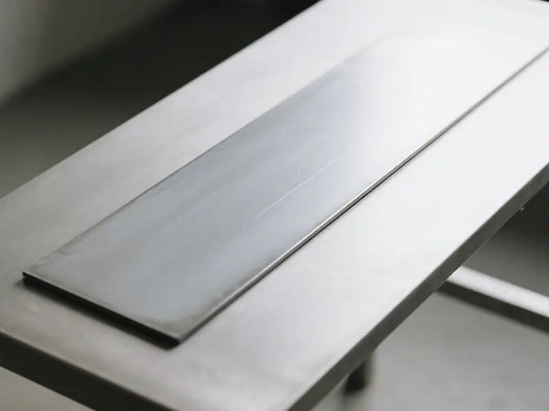
1. Cemented Carbide Substrate Materials (Tool Body)
| ISO Classification | Characteristics | Typical Grades (Domestic/International) | Main Composition | Performance Features | Suitable Materials for Machining |
|---|---|---|---|---|---|
| K Class | WC-Co based, no TiC, good toughness | Domestic: YG6, YG8, YG15 International: Sandvik H13A, Kennametal KCK30 | WC + 6%~15% Co | HRA hardness 88~91, strong impact resistance, moderate wear resistance; higher cobalt content results in better toughness | Cast iron (gray cast iron, ductile iron), non-ferrous metals (aluminum, copper alloys), plastics, wood |
| P Class | WC-TiC-Co based, excellent wear resistance | Domestic: YT15, YT14, YT5 International: Sandvik H10R, Kennametal KCP10 | WC + 5%~15% TiC + Co | HRA hardness 90~93, better wear resistance than Class K, lower toughness; higher TiC content leads to stronger wear resistance | Carbon steel, alloy structural steel (45# steel, 40Cr), forged steel, cast steel |
| M Class | WC-TiC-TaC-Co based, balanced performance | Domestic: YW1, YW2 International: Sandvik H16F, Tungaloy T9025 | WC + TiC + TaC + 6%~10% Co | HRA hardness 90~92, wear resistance between Class K and P, strong resistance to crater wear, moderate toughness | Stainless steel (304, 316), heat-resistant steel (1Cr18Ni9Ti), high-strength alloys (titanium alloys) |
| Ultrafine Grain | Grain size ≤0.5μm, high performance | Domestic: YG6X, YT05 International: Sandvik H01, Kennametal K4130 | Ultrafine WC + low Co (5%~8%) | HRA hardness 92~94, excellent wear resistance, slightly lower toughness than conventional Class K/P | High-precision machining (hardened steel HRC50+), precision die steel, high-speed finish milling |
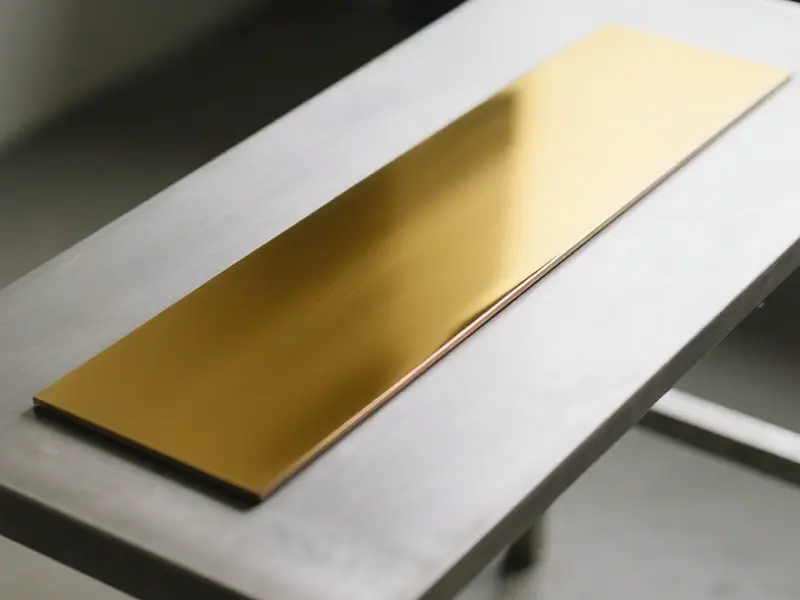
2. Coating Materials (Enhancing Surface Performance)
| Coating Type | Typical Composition | Performance Features | Application Scenarios | Matching Substrate Materials |
|---|---|---|---|---|
| TiN | Titanium Nitride | HV hardness 2000~2400, low friction coefficient (0.4~0.6), high-temperature resistance up to 500℃, golden yellow in color | Low-speed cutting (cutting speed ≤100m/min), wet cutting; suitable for machining carbon steel and cast iron | Class K, Class P |
| TiAlN | Titanium Aluminum Nitride | HV hardness 2800~3200, high-temperature resistance up to 800℃, good oxidation resistance, purplish gray in color | Medium to high-speed cutting (100~200m/min), dry/semi-dry cutting; suitable for machining alloy structural steel and stainless steel | Class P, Class M |
| AlTiN | Aluminum Titanium Nitride (higher Al content than Ti) | HV hardness 3000~3500, excellent high-temperature oxidation resistance up to 900℃, blackish gray in color | High-speed cutting (200~400m/min), dry cutting; suitable for machining high-strength steel, titanium alloys, and superalloys | Class M, ultrafine-grain alloys |
| CrN | Chromium Nitride | HV hardness 1800~2200, extremely low friction coefficient (0.2~0.3), strong corrosion resistance, silvery gray in color | Machining non-ferrous metals (aluminum, copper, to prevent adhesion), plastics, and composite materials; suitable for wet cutting | Class K (for aluminum/copper machining) |
| DLC | Diamond-Like Carbon | HV hardness 2000~4000, friction coefficient ≤0.1, high-temperature resistance up to 350℃, no adhesion to non-ferrous metals | High-speed machining of aluminum alloys (to prevent “built-up edge”), magnesium alloys, and carbon fiber composites | Class K (YG6, YG8) |
| TiCN | Titanium Carbonitride | HV hardness 2500~3000, better wear resistance than TiN, high-temperature resistance up to 400℃, grayish black in color | Medium-speed cutting of steel and cast iron, suitable for semi-finish/finish milling; balances wear resistance and lubricity | Class P, Class M |
Summary
- The cemented carbide substrate determines the basic performance of the tool (toughness, wear resistance) and should be selected from Class K/P/M according to the material to be machined.
- Coating materials can significantly extend tool life and should be matched based on cutting speed, cooling method, and the material being machined (e.g., AlTiN is suitable for high-speed dry cutting of steel, while DLC prevents adhesion in aluminum machining).
How to maintain and service Tungsten Carbide End Mill?
Maintaining end mills can effectively extend their service life, stabilize machining accuracy, and reduce production interruptions and cost losses caused by tool damage.
Environmental Control: Store in a dry, dust-free, and temperature-stable environment (humidity ≤ 60%) to avoid rusting of cutting edges due to moisture and dust adhesion.
- Unused end mills: Retain original packaging or cover with plastic protective sleeves to prevent cutting edges from colliding with each other.
- Long-shank end mills (e.g., deep-cavity end mills): Hang vertically or fix with brackets to avoid shank deformation.
Cleaning & Degreasing:
- Wipe the tool shank and tool holder bore with specialized cleaning agents (e.g., alcohol, tool cleaners) to remove oil (oil films cause loose clamping, leading to vibration and edge chipping).
- Avoid contact with hand sweat on cemented carbide end mills; apply anti-rust oil immediately after handling with bare hands.
- Visually check for cutting edge chipping or cracks (use a bright flashlight for side-illumination); inspect the shank for deformation or wear.
- For ball nose end mills: Ensure uniform ball radius; for corner radius end mills: Check the integrity of the corner radius.
Parameter Matching:
- Strictly follow the tool manual to set spindle speed, feed rate, and depth of cut (e.g., for cemented carbide end mills machining steel, feed per tooth exceeding 0.2mm may cause overload and edge chipping).
- For long overhangs (shank extension > 3×diameter): Reduce cutting parameters by 30% to avoid vibration-induced breakage.
- Prioritize high-pressure internal cooling (especially for deep cavity machining) with coolant flow ≥ 20L/min to flush chips promptly (chip accumulation dulls edges).
- Use emulsion for aluminum alloy machining (anti-sticking); use extreme pressure cutting oil for stainless steel/titanium alloy (enhanced lubrication).
- If unusual noise or vibration marks appear on the workpiece, immediately reduce feed rate or increase spindle speed (e.g., from 5000rpm to 6000rpm to break resonance).
- For narrow slot machining: Use variable pitch end mills (naturally vibration-resistant).
Timely Cleaning:
- Clean cutting edges and flutes with a soft brush + neutral cleaner (hard brushes damage coatings); use ultrasonic cleaning for stubborn chips.
- Dry with compressed air after cleaning to avoid residual moisture causing rust.
- Short-term storage (within 1 week): Apply a thin layer of anti-rust oil (prefer low-viscosity, easy-to-clean rust inhibitors).
- Long-term storage (over 1 month): Wrap with vapor phase rust preventive paper after oiling, then seal.
Regrinding Timing:
- Regrind immediately when flank wear ≥ 0.2mm (visible “bright wear band”) or when cutting force increases significantly (elevated machine load).
- Edges with chipping < 1/3 of edge length can be reground; replace if chipping exceeds half the edge length (avoid secondary cracking due to stress concentration).
- Equipment: Use diamond grinding wheels (grit 400~600#, dedicated for cemented carbide) with coolant during grinding to cool.
- Angle Control:
- Flat end mills: Relief angle 5°~8°, secondary relief angle 15°~20° (small angles for hard materials, large angles for soft materials).
- Ball nose end mills: Focus on regrinding the flank face; maintain ball radius accuracy (tolerance ≤ 0.01mm).
- After regrinding, check runout with a tool setter (≤ 0.01mm) to ensure uniform edges.
- Broken-edge end mills with sufficient remaining length: Shorten the shank (e.g., from 20mm edge length to 15mm) to repurpose as short-edge end mills (improved rigidity).
- Worn large-diameter end mills: Regrind to smaller diameters (e.g., φ16mm to φ14mm) for narrow slot machining.
- Cemented carbide end mills: High brittleness; avoid dropping during handling/clamping; never dry-grind (prone to edge burning).
- High-speed steel (HSS) end mills: Prioritize rust prevention; clean and oil daily in humid environments.
- Establish maintenance records: Track usage duration, machined materials, and regrinding times for each tool to predict lifespan (e.g., ≤3 regrinds for cemented carbide, ≤5 for HSS).
How long can a blade typically be used?
Clarifying the replacement cycle of end mills helps ensure stable machining accuracy and surface quality, avoids issues such as edge chipping and workpiece scrapping caused by excessive tool wear, and simultaneously controls tool consumption costs reasonably.
| Workpiece Material | Cutting Type | Flank Wear Threshold | Processing Performance Signals | Recommended Replacement Timing |
|---|---|---|---|---|
| Aluminum Alloy (Soft Material) | Regular Cutting | 0.25~0.3mm | Minor tool sticking marks on surface; slight increase in feed resistance | When wear reaches the threshold or surface roughness exceeds tolerance |
| Aluminum Alloy (Soft Material) | Heavy Cutting (Large Depth) | 0.2~0.25mm | Severe chip accumulation in flutes; dimensional fluctuation >0.02mm | Replace 10%~15% earlier than the threshold |
| Carbon Steel (e.g., 45# Steel) | Regular Cutting | 0.15~0.2mm | Dull cutting sound (“muffled noise”); appearance of vibration marks on workpiece surface | When wear reaches the threshold or before dimensional deviation |
| Stainless Steel (e.g., 304) | Regular Cutting | 0.1~0.15mm | Discoloration of chips (bluing); minor edge chipping on tool | Prioritize judgment based on processing performance signals |
| Hardened Steel (HRC50+) | Precision Milling | 0.08~0.1mm | Increase in surface roughness Ra value >20%; dimensional accuracy out of tolerance | Replace when wear approaches the threshold |
- Coated tools (e.g., TiAlN-coated) typically have a 30%~50% longer service life than uncoated tools, so their replacement cycle can be appropriately extended.
- For high-speed cutting (cutting speed >150m/min), wear accelerates, requiring a 20%~30% shorter replacement cycle.
- For critical processes (e.g., precision mold cavity machining), “stable processing accuracy” is the core principle—replace early rather than delay. For roughing, the threshold can be moderately relaxed to prioritize cost control.

