
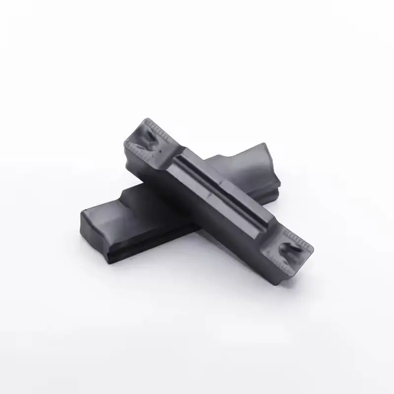
CNC Inserts
Engineered from tungsten carbide, they offer exceptional cutting efficiency and edge retention. Optimizing CNC machining processes, these inserts maintain consistent performance across diverse metal – working applications.
Application Scenarios
Processing different materials enables the manufacturing of diverse products across industries, meeting specific functional, performance, and application needs while driving technological innovation and industrial development.
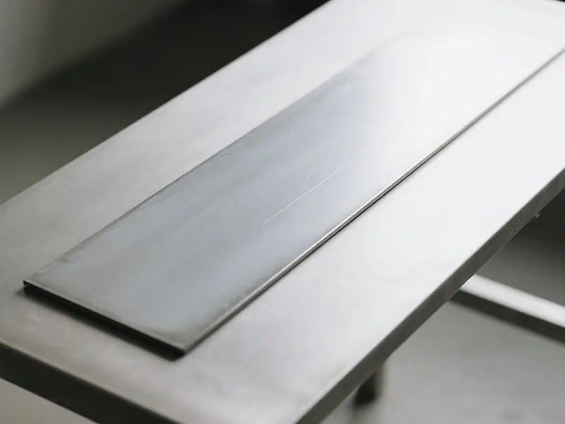
Ferrous Metals
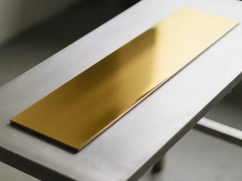
Non – Ferrous Metals
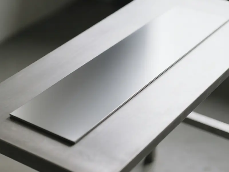
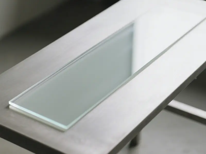
Plastics and Composite Materials
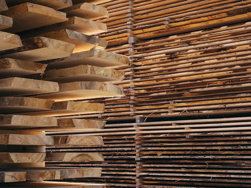
Wood and Plates
Uncover Your Needs with Us!
The dimensional accuracy and surface finish of the CNC insert seat, along with the insert’s cutting edge geometry, chip breaker design, coating properties, and substrate hardness, directly influence machining performance. Please share your specific application requirements (e.g., workpiece material, cutting parameters, desired surface quality) and provide relevant part drawings or samples. Our engineering team will tailor solutions including insert geometry, grade selection, and coating optimization to meet your exact needs.
What is a CNC Inserts ?
CNC cutting inserts are professional cutting tools for numerical control machines that work through controlled cutting motions (e.g., turning, milling) to precisely machine metals and alloys, featuring types like carbide (versatile) and ceramic (for hard materials), a structure of indexable blades with tool holders, and advantages of high precision, efficiency, and durability, serving as key tools in manufacturing industries (e.g., machinery, automotive) for automated CNC production.
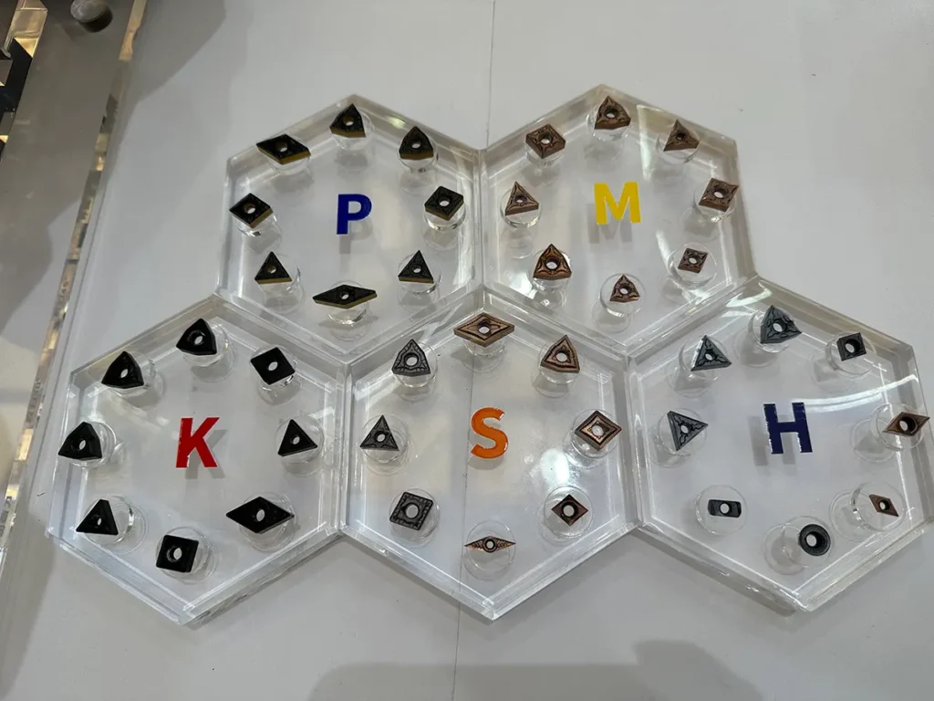
What are the common tool types used in CNC Inserts?
CNC insert types, via differentiated structural and performance designs, precisely adapt to machining processes like turning, milling, and drilling, addressing varied demands for shape, precision, and efficiency to enable comprehensive cutting capabilities.
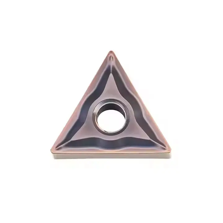
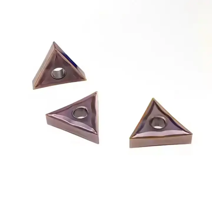
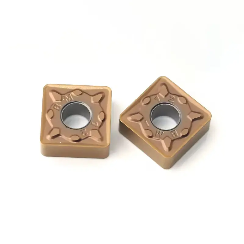
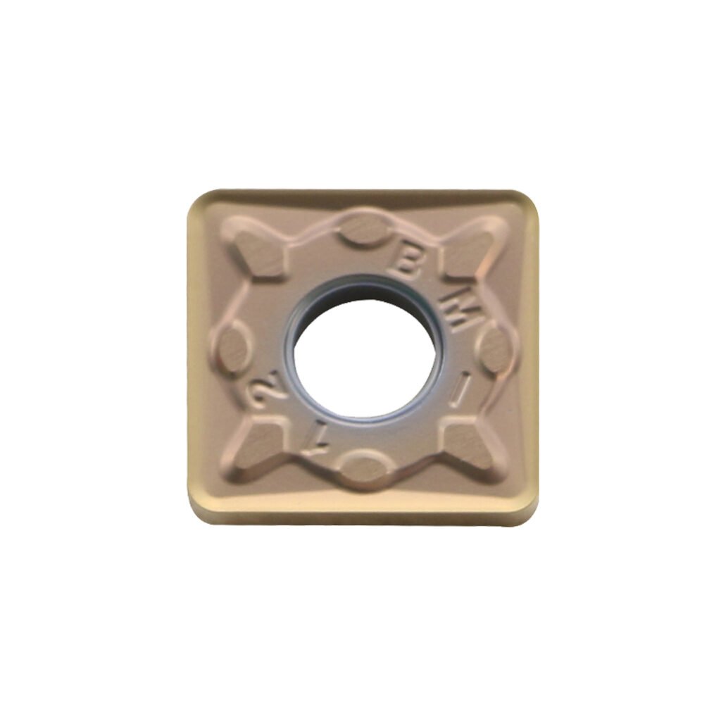
Turning Inserts
Structural Features: Available in geometric profiles (e.g., rhombic CNMG, triangular TNMG), featuring defined relief angles, nose radii, and chip – breaker grooves, compatible with lathe toolholders.
Functional Advantages: Enables high – precision continuous cutting (e.g., cylindrical/face turning), with controlled chip evacuation to prevent tool entanglement.
Typical Applications: Machining rotational components like crankshafts (automotive) and bearing races (machinery).
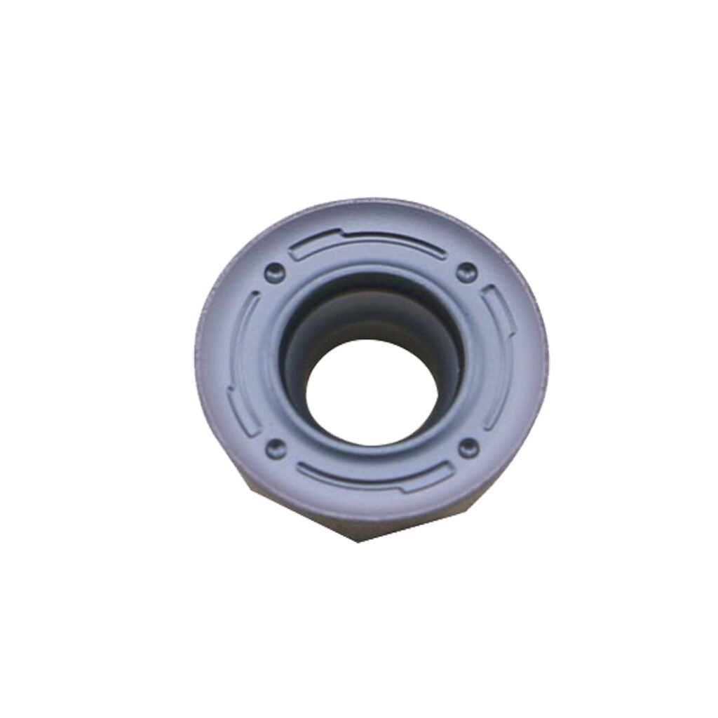
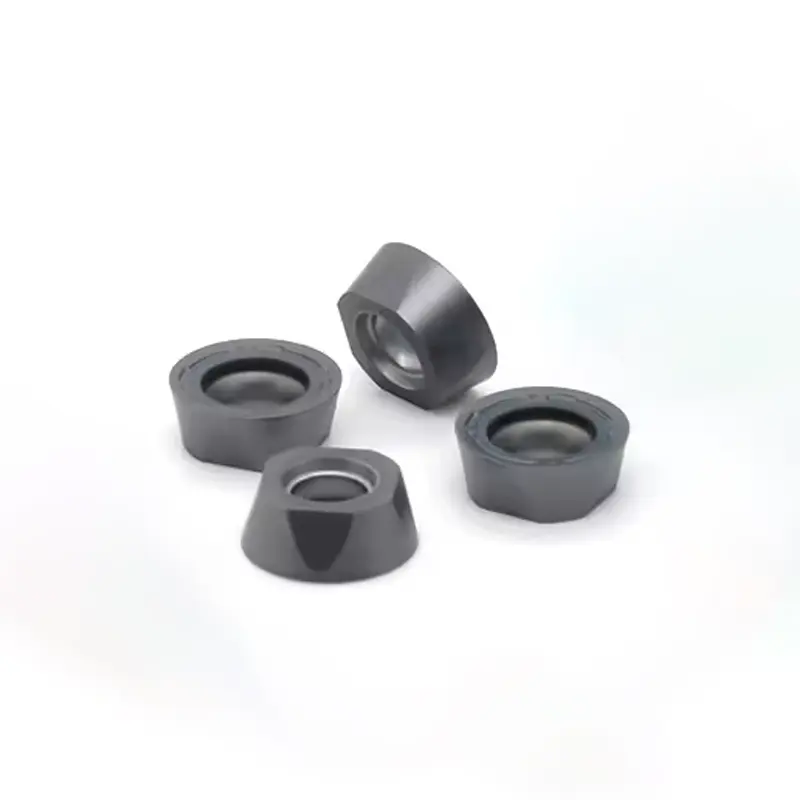
Milling Inserts
Structural Features: Multi – edge design (e.g., square SEKT, round RPMT), with helical cutting edges and specialized chip – forming grooves, integrated into end mills or face mills.
Functional Advantages: Achieves high – speed machining of complex 3D contours, with alternating cutting action to reduce thermal stress on the insert.
Typical Applications: Mold cavity profiling (die – making), aerospace structural part milling, and general engineering component facing.
Drilling Inserts
Structural Features: Equipped with a self – centering tip (e.g., split – point geometry), spiral flutes for chip removal, and carbide – tipped construction, assembled into drill bodies.
Functional Advantages: Ensures accurate hole centering and efficient deep – hole drilling, minimizing deflection in hard materials (e.g., alloy steel).
Typical Applications: Engine block hole production (automotive), hydraulic cylinder boring, and precision machinery bore finishing.
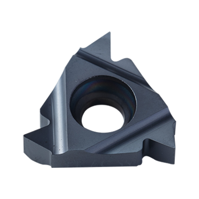
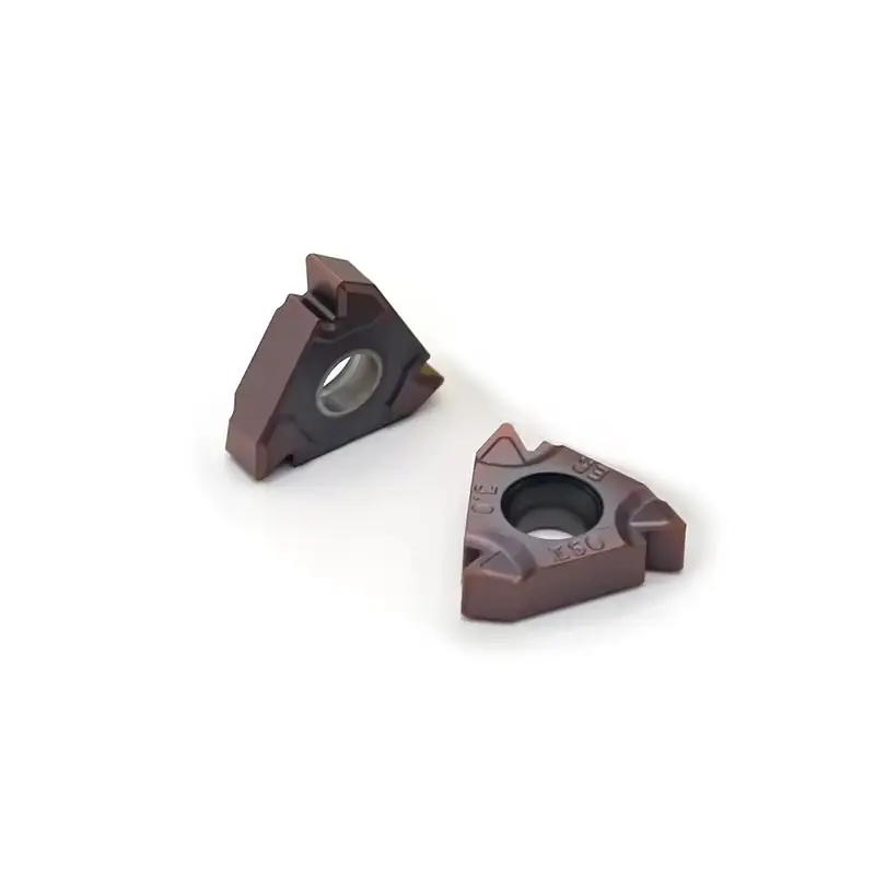
Threading Inserts
Structural Features: Precisely ground thread profiles (e.g., ISO, ACME), with reinforced tip geometry to resist chipping, compatible with threading toolholders.
Functional Advantages: Produces high – precision threads (class 6H/6g) with consistent pitch, suitable for both external and internal threading.
Typical Applications: Machining screws (construction), hydraulic fittings (fluid power), and transmission shafts (automotive).
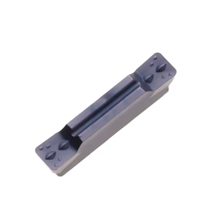
Cut - off & Grooving Inserts
Structural Features: Narrow cutting edge (width 1–5mm) with reinforced corner design, integrated into grooving/cut – off toolholders.
Functional Advantages: Enables efficient part separation (cut – off) and groove machining (annular/face grooves), with high impact resistance.
Typical Applications: Bar stock cutting in machine shops, groove turning on bearings, and slot machining in aerospace components.
What are the common working methods?
The turning, milling, drilling-boring, and cut-off/grooving operations of CNC inserts, through differentiated motion and cutting logics, respectively adapt to machining rotational parts, complex contours, hole systems, and groove/separation features, thus building full-dimensional cutting manufacturing capabilities for components.
Turning
- Principle: Uses the stationary cutting edge of the insert, with the workpiece rotating, and the insert feeding axially or radially to remove material.
- Scenario: Machining external circles, inner holes, end faces, threads (e.g., shafts, disk – shaped workpieces).
- Advantage: High precision, suitable for continuous cutting, with stable efficiency.
Milling
- Principle: Uses the rotating cutting edges of the milling cutter, with the insert rotating with the tool body and the workpiece feeding, achieving material removal through alternating cutting of teeth.
- Scenario: Machining planes, contours, cavities (e.g., molds, boxes).
- Advantage: High flexibility, capable of machining complex shapes, ideal for mass production.
Drilling / Boring
- Principle: Drilling uses a rotating drill with axial feeding to machine through holes or blind holes; boring refines and enlarges existing holes by fixed or rotating inserts.
- Scenario: Drilling for initial hole making, boring for precision hole finishing (e.g., engine cylinder holes).
- Advantage: Efficient hole making with drilling, precision improvement with boring, suitable for the entire hole – machining process.
Cutting - off & Grooving
- Principle: Uses the insert feeding laterally to cut off workpieces or machine grooves.
- Scenario: Cutting off bars, machining annular grooves or face grooves (e.g., shaft grooves, bar cutting).
- Advantage: Efficient for narrow grooves, fast cutting – off, ideal for special – shaped feature machining.
What parameters do we need to understand?
Understanding the parameters of CNC inserts enables the precise matching of processing materials, processes and equipment, avoids the mismatch of cutting performance, and ensures the controllability of processing efficiency, accuracy and cost.
Taking the typical model CNMG120408-PM as an example, the first 7 characters are mandatory parameters, and the last 3 are extended as needed:
| Position | Character | Meaning | Key Logic |
|---|---|---|---|
| 1st (Shape) | C | 80° diamond insert (Others: T – triangular/60°, S – square/90°, R – round/360°, D – 55° diamond, etc.) | The shape determines the nose angle, cutting direction, and applicable processes: – Triangular (T) → external turning; – Square (S) → facing/milling; – Round (R) → curved surface milling/impact resistance. |
| 2nd (Relief Angle) | N | 0° relief angle (Others: P – 11°, C – 7°, E – 20°, etc.) | A larger relief angle makes cutting sharper but the edge weaker: – For roughing, choose N (0°, double-sided use, impact-resistant); – For finishing, choose P (11°, smooth chip evacuation, bright surface). |
| 3rd (Precision Grade) | M | General precision (Others: G – precision grade, U – ultra-precision grade) | Precision determines mounting tolerance: – For CNC machining, choose G (small tolerance, nose runout ≤ 0.01mm); – For conventional machines, choose M (cost-effective). |
| 4th (Chip Breaker + Hole Geometry) | G | With round hole + double-sided chip breaker (Others: M – single-sided chip breaker, A – no chip breaker, T – countersunk hole chip breaker, etc.) | Chip breaker geometry determines chip control: – For steel workpieces, choose G (good chip curling, no tool wrapping); – For cast iron, choose K (wide chip breaker, anti-fracture); – For roughing, choose A (no chip breaker, impact-resistant). |
| 5th-6th (Cutting Edge Length) | 12 | Nominal cutting edge length 12.7mm (imperial conversion, e.g., 12 = 12.7mm, 16 = 16.5mm) | A longer edge enables a larger cutting width (efficient for roughing) but requires matching tool holder rigidity; For finishing, choose short edges (e.g., 09 = 9.525mm, high precision). |
| 7th-8th (Insert Thickness) | 04 | Nominal insert thickness 4.76mm (e.g., 04 = 4.76mm, 06 = 6.35mm) | A thicker insert has higher edge strength (for roughing/large cutting volume) but increased cutting resistance; For thin-walled machining, choose thin inserts (e.g., 03 = 3.97mm). |
| 9th-10th (Nose Radius) | 08 | Nose radius R0.8mm (e.g., 04 = R0.4mm, 12 = R1.2mm) | A larger nose radius improves surface roughness (for finishing) but is prone to vibration; For interrupted cutting, choose a small R (e.g., R0.2mm, anti-edge chipping). |
Suffixes typically convey information such as material, coating, and cutting direction, with varying rules across brands. Typical examples:
| Category | Code Examples | Meaning |
|---|---|---|
| Material/Coating | PM (Sandvik) | Cemented carbide substrate + TiAlN coating (general for steel workpieces, high-speed cutting) |
| AC8025P (Sumitomo) | Cemented carbide + Al₂O₃ coating (high-temperature wear resistance, cast iron roughing) | |
| CBN (Cubic Boron Nitride) | Superhard material, for machining hardened steel with HRC ≥ 45 (e.g., die steel) | |
| Cutting Direction | L (Left-hand tool) | Compatible with left-hand tool holders (e.g., reverse feed for internal turning) |
| Chip Breaker Subtype | CH (Toshiba) | Cast iron-specific chip breaker (short chips, anti-sticking) |
| Brand-Specific | GC4225 (Sandvik) | GC = cast iron machining series, 4 = TiAlN coating, 225 = performance grade (balanced wear resistance + toughness) |
- Milling inserts (e.g., APMT1135PDER)
1st character A: 85° parallelogram (suitable for shoulder milling, with multiple cutting edges);
4th character P: 11° relief angle (sharp, suitable for aluminum workpieces/finishing);
Numbers 1135: cutting edge length 11mm, thickness 3.5mm;
Suffix PDER: chip breaker geometry (general high-feed). - Thread inserts (e.g., 16ER100ISO-TF)
1st-2nd characters 16ER: 16mm size + right-hand external thread;
Number 100: pitch 1mm (metric ISO thread);
Suffix TF: wiper edge (improves thread precision). - Parting/grooving inserts (e.g., GB43R150)
1st character G: rectangular insert (parting-specific);
Number 43R150: width 1.5mm, suitable for 4mm cutting depth;
No relief angle (implied N, double-sided use, impact-resistant).
Take TNMG160408-MS (triangular turning insert) as an example:
T (triangular) → external turning, 60° nose angle, flexible feed;
N (0° relief angle) → double-sided use, strong edge, suitable for roughing/interrupted cutting;
M (general precision) → compatible with conventional tool holders;
G (default geometry, with hole + double-sided chip breaker) → universal for steel workpieces, controllable chips;
16 (edge length 16.5mm) → efficient for roughing;
04 (thickness 4.76mm) → impact-resistant;
08 (R0.8mm) → semi-finishing, surface Ra≤1.6μm;
MS (coating + material) → cemented carbide + TiN coating (wear-resistant at low speed, suitable for cast iron machining).
| Material Type | Code/Characteristics | Suitable Materials | Typical Scenarios |
|---|---|---|---|
| Cemented Carbide | P (steel), M (stainless steel), K (cast iron), N (aluminum/copper) | Steel, cast iron, non-ferrous metals | General machining (first choice for 80% of scenarios) |
| Ceramic/CBN | No specific code (see description), high hardness, high-temperature resistance | Hardened steel (HRC≥45), high-speed steel | Finishing of hard materials (e.g., hardened die parts) |
| Diamond (PCD) | No specific code, extremely wear-resistant but impact-sensitive | Aluminum/copper, non-metals (plastics/wood) | Mirror finishing (e.g., aluminum wheel hubs) |
| Coatings | TiN (gold, wear-resistant at low speed), TiAlN (gray, high-speed), Al₂O₃ (white, high-temperature resistant) | – | Choose TiAlN for high-speed cutting; Al₂O₃ for cast iron |
When purchasing, confirm the recommended three cutting parameters (affecting processing efficiency and insert life):
Cutting speed (Vc): e.g., 110-240m/min is recommended for stainless steel machining; for hard materials, choose low Vc (e.g., ≤80m/min for CBN machining of hardened steel).
Depth of cut (ap): Choose large ap (3-10mm) for roughing; small ap (≤1mm) for finishing.
Feed rate (f): Choose large f (0.3-0.5mm/r) for roughing; small f (≤0.2mm/r) for finishing.
| Functional Dimension | Key Parameters | Selection Logic |
|---|---|---|
| Chip Breaker Type | Suffix codes (e.g., GU – general, CH – cast iron, GR – high-feed) | Choose wide chip breakers for roughing (fast chip evacuation); narrow ones for finishing (short chips); “CH” for cast iron to prevent sticking. |
| Indexable Edge Count | Number of cutting edges (e.g., 8-edge milling inserts are more economical) | Choose multi-edge inserts for mass production (reduce per-edge cost); fewer edges for complex curved surfaces (higher edge strength). |
| Tool Holder Compatibility | Interface type (e.g., iLock, conventional groove) | Must match existing tool holders (avoid “inserts unused due to incompatible tool holders”). |
| Processing Scenario | Roughing (prioritize toughness: thick inserts, large R) vs. finishing (prioritize precision: small R, sharp edges) | Clarify the process: choose “impact-resistant type” for roughing and “ |
What materials can be used to make CNC Inserts?
By leveraging the performance differences of various materials, precisely match diverse machining objects and cutting conditions to ensure cutting efficiency, tool life, and machining quality.
1. WC-Co Series (No TiC, ISO K Class)
- Composition: WC as the matrix, Co as the binder (Co content: 8–15 wt.%), with no TiC or TaC added.
- Properties: High toughness and impact resistance, moderate wear resistance, and low sensitivity to built-up edges (BUE) from carbides in cast iron or non-ferrous metals.
- Applications: Inserts for machining cast iron (gray, ductile), non-ferrous metals (aluminum, copper alloys), and non-metallic materials.
- Typical Grades:
- YG6 (Co=6%, medium toughness, for roughing cast iron);
- YG8 (Co=8%, high toughness, for interrupted cutting of cast iron).
2. WC-TiC-Co Series (With TiC, ISO P Class)
- Composition: WC as the matrix, with 5–10 wt.% TiC (titanium carbide) added, Co content: 6–10 wt.%.
- Properties: Superior wear resistance to WC-Co grades, high oxidation resistance (TiC reduces chip adhesion), but lower toughness (TiC increases brittleness).
- Applications: Inserts for machining ferrous metals (carbon steel, cast steel, alloy structural steel), especially for continuous cutting or finishing.
- Typical Grades:
- YT15 (TiC=15%, high wear resistance, for finishing steel);
- YT5 (TiC=5%, higher toughness, for roughing steel).
3. WC-TiC-TaC (NbC)-Co Series (With TaC/NbC, ISO M Class)
- Composition: Based on WC-TiC-Co, with TaC (tantalum carbide) or NbC (niobium carbide) added, Co content: 8–12 wt.%.
- Properties: Excellent comprehensive performance — retains TiC’s anti-adhesion property, enhances high-temperature hardness and thermal shock resistance via TaC/NbC, with toughness between K and P classes.
- Applications: Inserts for difficult-to-machine materials (304/316 stainless steel, heat-resistant steel, high-strength steel), especially addressing work hardening and BUE in stainless steel.
- Typical Grades:
- YW1 (small TaC content, medium-speed stainless steel machining);
- YW2 (higher Co content, better toughness, for interrupted cutting of stainless steel).
4. Ultrafine-Grain Cemented Carbides
- Features: WC grain size ≤1μm (vs. 2–5μm in conventional grades), Co content: 5–10 wt.%, with small TiC/TaC additions optional.
- Properties: Significantly improved hardness (HRA up to 93–94) and wear resistance while retaining moderate toughness, ideal for high-precision and high-speed cutting.
- Applications: Ultra-fine edge inserts for aluminum alloys (anti-burring in high-speed cutting), precision die steel (finishing), and high-strength alloys.
5. High-Performance Alloys With TaC/NbC (For Difficult-to-Machine Materials)
- Composition: High proportion of TaC/NbC (10–20 wt.%), low Co content (5–8 wt.%), WC as the matrix.
- Properties: Extreme high-temperature stability (>1000℃), outstanding resistance to crater wear.
- Applications: Inserts for materials with poor thermal conductivity and high-temperature wear (e.g., TC4 titanium alloy, Inconel 718 superalloy).
Material Selection Logic
The core principle for selecting cemented carbides for CNC inserts is performance matching:- Cast iron: WC-Co (K class, high toughness);
- Steel: WC-TiC-Co (P class, high wear resistance);
- Stainless steel/difficult materials: WC-TiC-TaC (M class, balanced performance);
- High-precision machining: Ultrafine-grain carbides.
In practice, these alloys often act as insert substrates, further enhanced by coatings (e.g., TiAlN, AlCrN) to optimize performance.Key Technical Notes:
- Terminology: ISO classes (K/P/M) align with material application ranges (cast iron/steel/stainless steel).
- Properties: Emphasize trade-offs (e.g., TiC improves wear resistance but reduces toughness).
- Grades: Retain Chinese grade designations (YG/YT/YW) with explanatory notes for clarity.
This structure ensures clear differentiation between alloy systems, guiding precise material selection for specific machining tasks.
How to maintain and service CNC Inserts?
Maintaining and servicing CNC blades can delay wear, avoid damages such as blade breakage, ensure processing accuracy and stability, extend the tool life and reduce production losses.
I. Storage Management: Prevent Cutting Edge Damage
Environmental Control:
- Rust formation on cemented carbide inserts due to moisture;
- Chip adhesion on coated insert edges (dust accumulates on coatings, causing abrasion).
Protection & Isolation:
- Unused indexable inserts: Retain original packaging or store in pad-protected cases to prevent edge chipping/collision.
- Form blades (e.g., thread/grooving blades): Store separately to avoid profile deformation from mechanical stress.
Categorization & Labeling:
- Model (e.g., TNMG160408),
- Material (cemented carbide/ceramic/CBN),
- Edge condition (unused/used/indexable).
Label wear levels to avoid misusing worn-out edges.
II. Pre-Use: Critical Checks Before Clamping
Cleaning & Degreasing:
- Clean tool holder clamping surfaces and insert pockets with specialized cleaners (alcohol, tool cleaner) to remove oil (oil films reduce clamping force, causing vibration/chipping).
- For coated inserts: Avoid direct contact with sweaty hands; clean fingerprints from edges immediately (sweat corrodes coatings).
Visual Inspection:
- Inspect edges under strong side illumination for:
- Chipping, cracks, or local coating delamination (delaminated areas accelerate wear).
- For indexable inserts: Verify uniform nose radius.
- For form blades (e.g., thread blades): Check thread/profile integrity.
III. During Machining: Control Cutting Conditions to Reduce Damage
Parameter Matching:
- Follow insert specifications for spindle speed, feed rate, and depth of cut:
- Example: Cemented carbide on steel → feed rates > 0.3mm/r cause overload; ceramic inserts require ≥200m/min for efficiency.
- For interrupted cutting (e.g., slots, steps): Reduce parameters by 20–30% to avoid impact chipping.
Cooling & Chip Evacuation:
- Prioritize high-pressure internal coolant (especially for deep-hole boring); ensure flow ≥15L/min to flush chips (buildup scratches edges).
- Coolant choices:
- Kerosene for aluminum (anti-sticking);
- Extreme-pressure cutting oil for stainless steel/titanium (lubrication);
- Dry cutting for cast iron roughing (avoids graphite adhesion).
Vibration Monitoring:
- If unusual noise or vibration marks appear: Adjust feed rate or spindle speed (e.g., 3000rpm → 3500rpm to break resonance).
- For thin-walled parts: Use small nose radius inserts (e.g., R0.2mm) – inherently vibration-resistant.
IV. Post-Use: Cleaning + Protection for Extended Life
Timely Cleaning:
- Clean edges and chip breakers with a soft brush + neutral cleaner (avoid coating damage). For stubborn chips: Ultrasonic cleaning (≤5 minutes to prevent delamination).
- For cemented carbide inserts with built-up edges (BUE): Gently scrape with a bamboo strip (metal tools scratch edges).
Rust Prevention & Storage:
- After cleaning, air-dry:
- Coated inserts: No oil (affects clamping precision);
- Cemented carbide inserts: Apply a thin anti-rust oil layer.
- For indexable inserts: Mark worn surfaces post-indexing; collect worn inserts centrally (avoid mix-ups).
Wear Evaluation:
- Measure flank wear land width (e.g., ≥0.3mm for cemented carbide on steel → index/replace).
- For form blades (e.g., thread blades): Check thread/profile wear; discard if precision exceeds tolerance.
Key Technical Notes:
- Indexable inserts: Focus on preventing edge collision during storage.
- Coated inserts: Minimize human contact to avoid coating corrosion.
- Form blades: Prioritize profile integrity during storage and inspection.

