
Center Drill
Center drills are specialized cutting tools used to create precision center holes in workpieces, facilitating accurate alignment and guiding for subsequent drilling or machining operations, with their shank smoothness, concentricity, and cutting – part features influencing the centering quality, and customized production available based on specific requirements along with relevant drawings/samples.
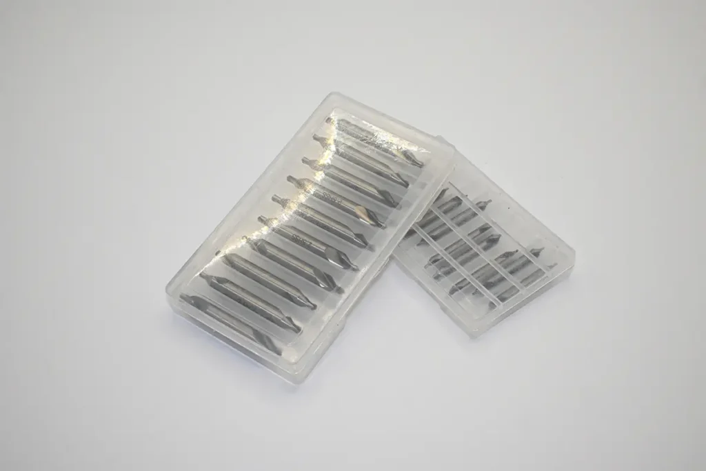
Products Provided by Kedel
Need custom blades? We design and make them
Application Scenarios
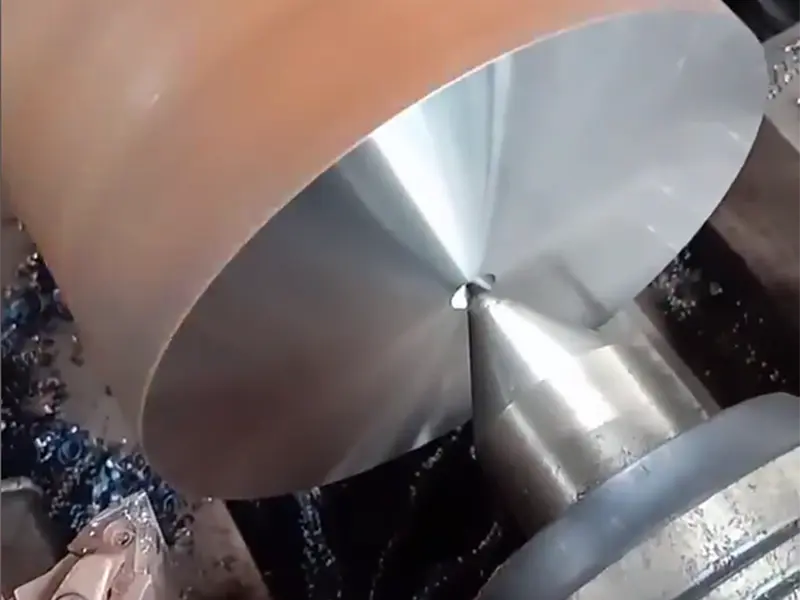
When a center drill is used for positioning a twist drill, it prevents drilling deviation by pre-drilling an accurate center hole, ensuring hole position precision; when used for center positioning in grinding machine processing, it ensures the stability of the workpiece’s rotational axis with the center hole’s conical surface as a reference, guaranteeing the form and position accuracy of grinding. Both are key means to improve machining precision by establishing reliable references.
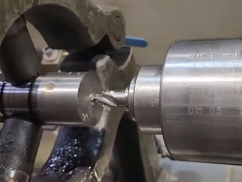
Drilling Orientation for Drill Press / Milling Machine
Uncover Your Needs with Us!
The smoothness and concentricity of the center drill shank, as well as the edge geometry, flute shape, helix angle and hardness of the center drill cutting part are all closely related to the centering effect. Please inform us of your or your customers’ specific centering requirements, and provide relevant drawings or samples. We will carry out customized production accordingly.
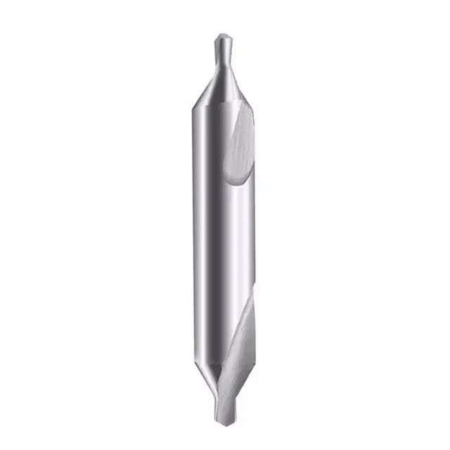
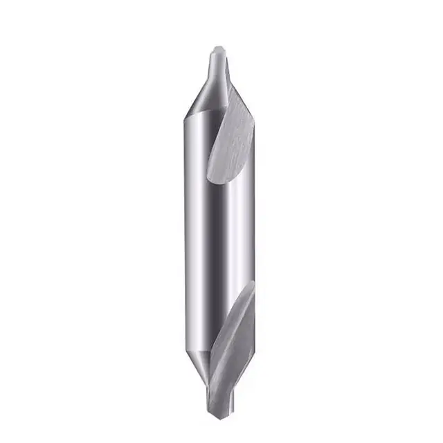
What is a Center Drill ?
A center drill is a specialized cutting tool designed to create center holes (60° conical or composite conical – cylindrical holes) in workpieces. It operates by rotating and feeding axially into pre – processed surfaces (e.g., flat ends of shafts), with its conical cutting edges shearing material to form precise centering features. Center drills are categorized into types like Type A (without a protective cone, for basic centering) and Type B (with a 120° protective cone, optimized for precision machining setups), along with extended – shank variants for deep – face centering tasks. Constructed from materials such as high – speed steel (versatile for general centering tasks) and carbide (ideal for machining high – hardness materials or high – speed applications), they feature fluted configurations (straight, spiral, etc.) to enable efficient chip removal from the conical cavity. Boasting advantages like facilitating accurate positioning for subsequent operations (e.g., turning, grinding), adapting to diverse production scales (ranging from small – batch prototyping to large – scale mass production), and being compatible with various materials (metals and certain alloys), center drills act as indispensable tools in manufacturing sectors (e.g., machinery, automotive, aerospace) for establishing centering references in both automated and manual production workflows.
What are the common tool types used in Center Drill?
Different types of center drills adapt to scenarios like basic positioning and high-precision protection in the machining of rotational parts through differentiated configurations, ensuring the accuracy and stability of center holes as positioning references.
Type A Center Drill
Structural Features: Composed of a cylindrical shank and a 60° conical tip (no protective cone), featuring defined relief angles on the cone and a smooth shank, compatible with standard lathe toolholders.
Functional Advantages: Enables high-precision center hole drilling (e.g., on shaft ends), with controlled chip evacuation to prevent tool clogging.
Typical Applications: Machining simple shafts (general machinery) and small-batch automotive pins, providing centering for basic turning/grinding.
Type B Center Drill
Structural Features: Integrates a cylindrical shank, 60° working cone, and 120° protective cone, featuring optimized relief angles on both cones and reinforced flutes, compatible with precision lathe toolholders.
Functional Advantages: Ensures sustained centering accuracy in complex machining (e.g., multi-step grinding), with the 120° cone shielding the 60° surface from clamping damage.
Typical Applications: Machining engine crankshafts (automotive) and precision bearing races (aerospace),
What are the common working methods?
Different operating modes of center drills, through differentiated machining patterns, respectively meet the needs for precision establishment, maintenance, and restoration of center holes in rotational workpieces across scenarios of new fabrication, mass production, and repair, thereby ensuring the reliability of the positioning reference for subsequent processes such as turning and grinding.
Manual Centering Machining
- Principle: Manually control the axial feeding of the center drill via a lathe tailstock handwheel, with the workpiece stationary or rotating at a low speed, to machine 60° conical center holes.
- Application Scenarios: Machining center holes for simple shafts in general machinery, small – batch prototypes, or correcting misaligned center holes.
- Advantage: High flexibility for single – piece or small – batch machining, allowing real – time visual adjustment of the feeding depth.
CNC - Synchronized Centering
- Principle: Integrate the center drill into CNC turning/milling programs to automatically control axial feeding, with the workpiece rotating synchronously as needed, achieving high – precision centering.
- Application Scenarios: Machining critical rotational parts such as aerospace engine shafts and precision gear blanks, providing ultra – high – precision positioning references for subsequent grinding and turning.
- Advantage: Positioning accuracy up to ±0.01mm, good consistency in mass production, and reduced setup time for multi – process integration.
Center Hole Reconditioning
- Principle: Use the center drill for light cutting on existing center holes to remove the worn or deformed layers on the 60° conical surface and restore positioning accuracy.
- Application Scenarios: Refurbishing center holes of mold core pins, repairing used shafts, or correcting deformed center holes after heat treatment.
- Advantage: No need to re – manufacture the workpiece, extending its service life; cost – effectively maintaining the continuity of centering accuracy in multi – process machining.
What parameters do we need to understand?
Understanding parameters such as the cone angle, diameter, and material of center drills enables precise matching of workpiece positioning requirements, ensures the accuracy of center holes, and supports the stability and consistency of subsequent machining processes.
I. Shank and Overall Parameters of Center Drills
- Straight shank: Compatible with lathe tailstocks and drill chucks, general – purpose, suitable for small – to – medium – diameter center drills (e.g., φ1–φ5mm).
- Morse taper shank: Enhances rigidity for large – diameter center drills (e.g., φ6mm and above) or heavy – duty machining (e.g., centering forged blanks), reducing vibration and runout.
- Extended shank: Allows replacing with an extension rod, suitable for centering deep – hole end faces (e.g., long – shaft end machining), controlling overhang to avoid bending deformation.
Refers to the total length including the shank and cutting section. After clamping, the overhang is usually ≤ 3 times the center drill diameter (to avoid chatter during high – speed rotation), and it must match the machine tool’s Z – axis stroke.
II. Cutting Geometry Parameters
- 60° working cone angle: Tolerance is typically ±15′–±30′, directly determining the fit accuracy with the machine center (excessive tolerance causes positioning deviation).
- 120° protective cone (Type B only): Protects the 60° cone surface; the protective cone angle tolerance is ±30′, preventing damage to the positioning surface from center impacts during clamping.
- Small radius (R≤0.1mm): Suits high – precision centering (e.g., precision shafts), minimizing the fit gap between the center hole and the center.
- Large radius (R≥0.2mm): Enhances tip strength, suitable for rough centering of blank workpieces (e.g., cast – iron end faces), with better chipping resistance.
- Straight flute: Simple chip evacuation, general – purpose, suitable for centering mild steel and aluminum workpieces, easy to regrind.
- Spiral flute (small helix angle ≤15°): Assists chip evacuation, preventing chip accumulation on the 60° cone surface, suitable for deep – center – hole machining (e.g., long – shaft end faces).
III. Material and Coating Parameters
- High – speed steel (HSS): Cost – effective, general – purpose, suitable for centering carbon steel and alloy steel; common grades include M2 (standard) and M35 (cobalt – containing, better heat resistance, suitable for interrupted cutting).
- Carbide: High hardness and wear resistance, suitable for high – hardness materials (e.g., quenched steel ≥50HRC) or high – speed centering; brittle, requiring high machine tool rigidity.
- Powder metallurgy high – speed steel: Fine – grained structure, excellent precision stability, suitable for ultra – precise centering (e.g., aerospace engine shafts).
- Titanium nitride (TiN): General – purpose, improves lubricity/wear resistance, suitable for centering non – ferrous and ferrous metals, reducing chip adhesion.
- Titanium aluminum nitride (TiAlN): Excellent high – temperature stability, suitable for high – speed centering of stainless steel and quenched steel, resisting thermal softening of the cutting edge.
- Chromium nitride (CrN): Corrosion – resistant, suitable for aluminum, copper, and humid environments, preventing rust on the center drill that affects precision.
What materials can be used to make Center Drill?
Taps made of different grades of cemented carbide are designed to precisely match the characteristics of various work materials and cutting conditions by adjusting their composition and performance, thereby achieving efficient, stable, and economical thread machining.
I. High-Speed Steel (HSS)
1. Conventional High-Speed Steel (Representative Grades: W6Mo5Cr4V2, 4241, 4341)
- Composition: Contains tungsten (W), molybdenum (Mo), chromium (Cr), and vanadium (V), with a cobalt-free or low-alloy design.
- Properties: Hardness ranges from 63–66HRC, cost-effective, combining toughness and wear resistance, with excellent chipping resistance.
- Applications: Suitable for centering conventional metals (e.g., carbon steel, alloy steel, aluminum, copper), such as basic center hole machining for common shafts and disk-shaped workpieces.
2. Cobalt-Containing High-Speed Steel (HSS–Co, Representative Grades: M35, Cobalt-Alloyed 6542)
- Composition: Based on conventional HSS with ~5% cobalt (Co) added to enhance high-temperature performance.
- Properties: Superior heat and wear resistance compared to standard HSS; slower hardness degradation at high cutting temperatures.
- Applications: Compatible with difficult-to-machine materials (e.g., stainless steel, heat-resistant alloys) or high-speed centering in CNC lathes.
II. Cemented Carbide
1. Solid Cemented Carbide
- Composition: A powder metallurgical alloy with tungsten carbide (WC) as the matrix.
- Properties: Hardness ≥90HRA, extremely wear-resistant, enabling higher cutting speeds; however, it is brittle and has low impact resistance.
- Applications: Suitable for high-hardness workpieces (e.g., quenched steel ≥50HRC, titanium alloys) or large-scale automated centering (requiring high machine tool rigidity).
2. Cemented Carbide-Tipped (Composite Structure)
- Structure: The tool body is HSS, with cutting edges tipped with cemented carbide.
- Properties: Combines cemented carbide’s wear resistance and HSS’s toughness, at a lower cost than solid carbide.
- Applications: Balancing precision and economy, ideal for high-precision centering of medium-hardness materials (e.g., mold core shafts, precision gear blanks).
III. Materials for Special Scenarios
1. Powder Metallurgy High-Speed Steel (HSS–PM)
- Process: Sintered via powder metallurgy, with a fine, uniform structure.
- Properties: Hardness is 2–3HRC higher than conventional HSS, with better toughness and extremely stable precision.
- Applications: Ultra-high-precision center hole machining for aerospace engine turbine shafts, medical implants, etc.
2. Coating Enhancement (Performance-Enabling Layer, Not the Base Material)
- Common Types:
- TiN (Titanium Nitride): General-purpose, improving lubricity and wear resistance, compatible with most metals.
- TiAlN (Titanium Aluminum Nitride): Excellent high-temperature stability, suitable for high-speed centering of stainless steel/quenched steel.
- CrN (Chromium Nitride): Corrosion-resistant, compatible with soft metals (e.g., aluminum/copper) and humid environments, preventing center drill rust.
- Function: Forms a protective film on the base material, extending service life and improving machining precision (requires matching the base material).
How to maintain and service Center Drill ?
Maintaining and servicing center drills can preserve their cutting precision and service life, ensure the stability of the center hole as a positioning reference, and reduce machining deviations of workpieces as well as tool wear.
I. Operational Guidelines: Avoiding Damage Sources
- Control Cutting Parameters: Select rotational speeds based on materials (e.g., ≤3000r/min for HSS drilling carbon steel; up to 5000r/min for cemented carbide drilling quenched steel), with a feed rate ≤0.05mm/r to prevent chipping from overload or tempering due to overheating.
- Avoid Intermittent Impact: Chamfer rough surfaces before centering to reduce sudden loads on the tool; ensure machine spindle runout ≤0.01mm to prevent accelerated wear from eccentricity.
II. Immediate Cleaning and Rust Prevention
- Post-Processing Cleaning: Immediately remove chips from flutes (especially spiral flutes) using a brush or compressed air; wipe the tool body with a neutral cleaner to remove oil, metal debris (preventing adhesion and corrosion of aluminum/copper chips).
- Short-Term Rust Prevention: Apply a thin rust-preventive oil to unused tools (avoiding cutting edges to preserve next-use precision); inspect daily in humid environments.
III. Proper Re-Sharpening and Precision Maintenance
- Re-Sharpening Timing: Re-sharpen when the center hole shows uneven conical surfaces, positioning deviation >0.02mm, or increased cutting resistance.
- Re-Sharpening Standards: Use specialized equipment (e.g., center drill grinders) to ensure a 60° cone angle tolerance of ±15′ and a nose radius (R) deviation ≤0.01mm; use diamond wheels for cemented carbide center drills to avoid chipping.
IV. Storage and Regular Inspection
- Categorized Storage: Store by model/material (HSS, cemented carbide) in boxes with soft liners to prevent edge chipping from collisions.
- Regular Verification: Weekly check cutting edge integrity (no chipping/rolling) and shank precision (straight shank roundness deviation ≤0.01mm); discard or re-sharpen worn tools beyond limits.
V. Maintenance for Special Materials
- High-Speed Steel (HSS): Avoid moisture contact; apply anti-rust grease for long-term storage; post-sharpening, stress-relieve via low-temperature tempering (200–250°C) to prevent cracking.
- Cemented Carbide: Never impact or drop; ensure sufficient cooling during re-sharpening to avoid thermal shock cracking; clamp only the shank during setup, avoiding contact with cutting edges.
How long can Center Drill typically be used?
Timely replacing worn or damaged center drills can avoid centering deviations, ensure the precision of subsequent machining and the quality of workpieces, and reduce scrap rates and cost losses.
| Category | Specific Phenomena | Impact on Machining | Replacement Recommendations |
|---|---|---|---|
| Cutting Edge Wear | 1. Obvious blunting with a continuous rounded edge (HSS > 0.1mm, cemented carbide > 0.05mm). 2. Obvious burrs or a “chattering” sound during cutting. | Center hole surface roughness (Ra > 1.6μm) and increased cutting resistance. | Replace immediately. |
| Flute Anomalies | 1. Severe flute clogging, repeated chip jamming even after cleaning. 2. Flute wall wear reduces chip evacuation space. | Surging cutting temperature causes tool tempering and potential edge chipping. | Replace immediately if cleaning fails. |
| Machining Precision Deviation | 1. Perpendicularity deviation between the center hole cone and axis > 0.02mm. 2. Positioning deviation > 0.02mm (measured with a dial indicator). 3. Center hole diameter > 0.1mm larger than the standard. | Subsequent machining (e.g., turning, grinding) leads to workpiece eccentricity, runout deviation, and higher scrap rates. | Replace immediately. |
| Physical Tool Damage | 1. Cutting edge chipping (notch depth > 0.2mm). 2. Tip breakage or partial loss. 3. Shank deformation (roundness deviation > 0.03mm). | Fails to ensure centering precision; may scratch the workpiece or damage the machine spindle. | Replace immediately; do not reuse. |
| Material-Specific Wear | 1. For HSS machining high-hardness materials (>45HRC), <50 workpieces per regrind. 2. Adhesive wear on the edge when machining stainless steel/titanium alloys. | Unstable center hole dimensions and frequent “flared mouth” defects. | Inspect in advance; replace after reaching the cumulative machining volume standard. |
Supplementary Notes
- For HSS center drills, mandatory inspection is recommended after machining 500–800 ordinary steel workpieces; for cemented carbide, this can be increased to 1000–1500 pieces (adjust based on the machined material).
- When machining soft metals (aluminum/copper), if “tool sticking” in the center hole due to chip adhesion on the cutting edge recurs after cleaning, inspect the edge condition and replace if necessary.
- Before mass production, test-drill 1–2 workpieces; only proceed with mass production after confirming qualified center holes to avoid batch scrap due to tool issues.

