
Metal Cutting Blade
A metal cutting tool is an industrial tool installed on various cutting equipment, which processes materials such as steel plates, steel pipes, and metal coils into specified shapes or sizes through mechanical shearing, cutting, thermal methods, etc.
Products Provided by Kedel
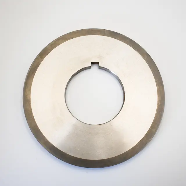
Pressure Slitting Top Blade
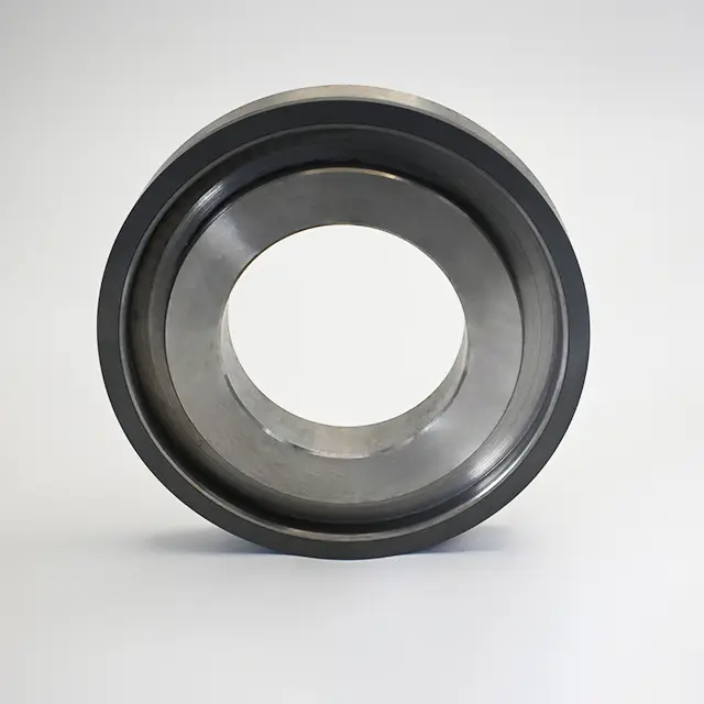
Pressure Slitting Bottom Blade
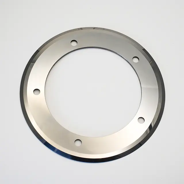
Shear Circular Blade
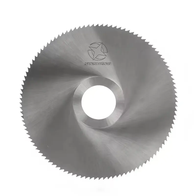
Circular Saw Blade
Click the image to view product details
Need custom blades? We design and make them
Application Scenarios
Metal slitting knives precisely slit stainless steel, aluminum, and copper coils to provide raw materials of suitable widths for downstream sectors like kitchenware, electronics, and packaging, supporting product manufacturing.
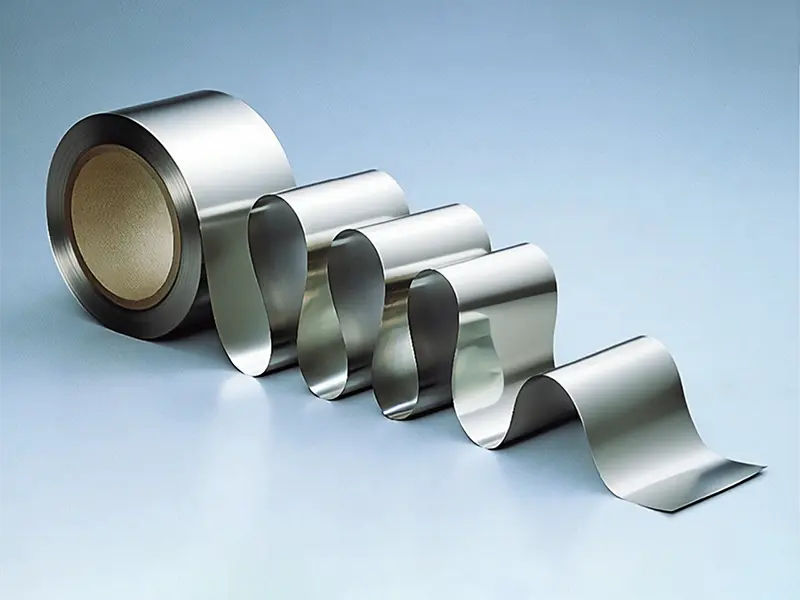
stainless steel coil
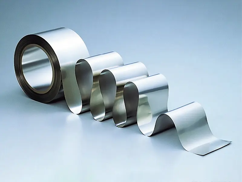
aluminum coil
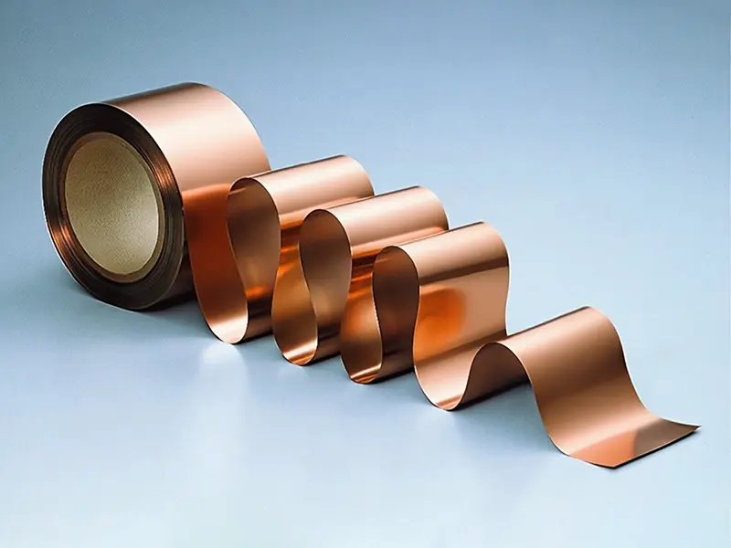
Copper coil
Uncover Your Needs with Us!
If you have customization needs for metal slitting blades (including non – edged moving blades, fixed blades, edged circular blades, and serrated circular blades), please feel free to contact us! Provide details like the brand/model of slitting equipment (e.g., slitting machines, rotary shears), tool holder installation dimensions, blade performance requirements (material, precision, wear resistance), and actual working conditions (metal type, thickness, production speed). Our engineers will craft a tailored solution and follow up within 72 hours to boost your metal slitting efficiency and quality.
What is a Metal Cutting Blade?
The circular blades for rotary shears are industrial cutting tools that longitudinally slit metal coils (such as steel strips and aluminum coils) into specified widths. Achieving continuous processing through the high-speed rotational shearing of upper and lower blades, they suit 0.1-8mm metal materials with a slitting tolerance of ±0.1mm and minimal burrs. Widely used in mass slitting production for steel, automotive, and other industries.
What are the common tool types used in Metal Cutting Blade slitting?
Circular blades suit high-speed metal cutting/pressing. Bottom blades ensure shearing edge quality. Saw blades cut through thick/hard metals. Their structural differences meet efficiency/precision needs in various metal processing.
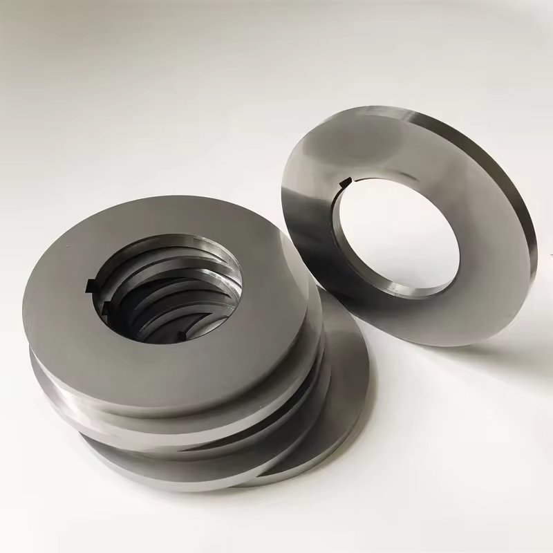
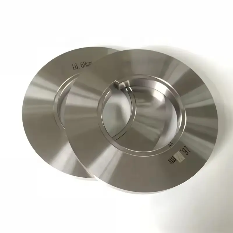
Circular Blade,Including Edgeless & Edged Types
Structural Features: Disk – shaped with a central mounting hole. The cutting edge can be a continuous sharp edge (edged) or a smooth arc surface (edgeless), and the blade thickness is tailored to metal slitting/forming needs, enabling high – speed rotational operation.
Functional Advantages: During metal processing, edged blades ensure cutting precision with smooth edges, while edgeless blades shape materials via pressure. Both adapt to high – speed production lines, reducing material deformation or edge defects to improve processing consistency.
Typical Applications: In lithium – ion battery electrode slitting (edged for foil cutting, edgeless for embossing), and metal coil rolling forming. It slits or shapes large rolls into narrow strips or specific surface textures for component manufacturing.
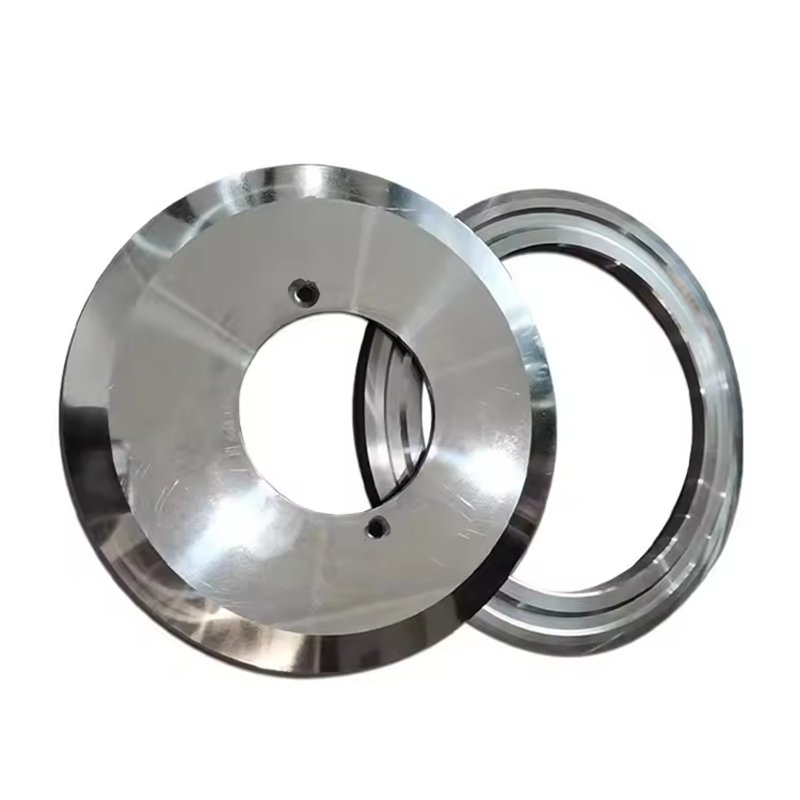
Bottom Blade
Structural Features: Usually a fixed or low – speed rotating plate – like/disk – shaped blade. The cutting edge is designed as a wear – resistant flat or arc surface. Its thickness and hardness match stamping/shearing loads, enabling stable supporting cutting.
Functional Advantages: As a shear – pair blade, it cooperates with the moving blade to achieve stable shearing. The wear – resistant structure ensures edge precision during long – term use, reducing shearing burrs. It adapts to medium – low speed stamping lines to improve workpiece edge quality.
Typical Applications: In metal sheet stamping (e.g., hardware blanking) and leather/metal strip shearing. It acts as a fixed edge cooperating with the moving blade to separate materials, meeting part dimension precision requirements.
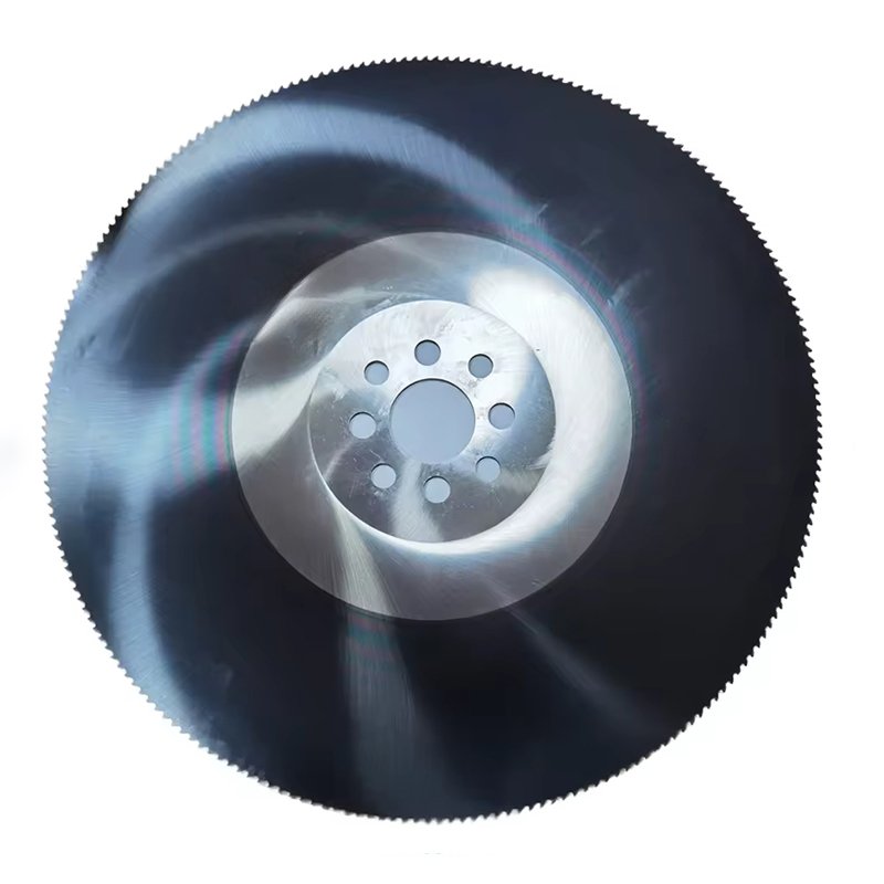
Saw Blade
Structural Features: Disk – shaped with serrated cutting edges distributed around the perimeter and a central mounting hole. The tooth profile and thickness are tailored to hard material cutting, enabling high – speed rotational sawing.
Functional Advantages: The serrated cutting action breaks the strength of thick and hard metals through intermittent cutting. It adapts to high – hardness/thick – wall materials, with high sawing efficiency, controllable cuts, and reduced material deformation to ensure thick – material slitting precision.
Typical Applications: In stainless steel pipe sawing, thick steel plate slitting, and titanium alloy bar cutting. It slits large – sized workpieces into fixed – length segments or narrow strips to meet structural part processing dimension requirements.
What are the common working methods?
Press slitting ensures the surface integrity of soft and thin metals during slitting; circular shear slitting supports the continuous high-speed processing of metal coils; saw cutting breaks through the slitting strength barrier of thick and hard metal workpieces.
Circular Shear Slitting
Circular Shear Slitting uses paired rotating circular blades (or cooperating with a fixed blade) to slit materials in a rolling – shear manner. It is suitable for the continuous and high – speed slitting of metal coils, like steel strips for automotive component manufacturing.
Saw Slitting
Saw Slitting uses a serrated circular blade to slit materials via a sawing action. It is suitable for slitting thick and hard metal workpieces, such as stainless steel plates for industrial structural parts.
Pressure Slitting
Pressure Slitting uses a non – edged blade to slit materials through plastic deformation under pressure. It is suitable for slitting soft and thin metal coils, such as aluminum foil in the flexible packaging industry.
What materials can be used to make cutting blades?
Based on the hardness, thickness of processed materials, and differences in operational conditions, cemented carbide materials with different compositions (such as TiC/YG types) and properties (wear resistance/impact resistance) are selected to achieve the optimal balance among slitting efficiency, tool life, and machining precision.
| Shear Slitting | YT15, YW1 | P10~P20 | Steel strip, stainless steel strip (0.5-3mm) |
| YG6, YG8 | K10~K20 | Aluminum strip, copper strip, cast iron sheets (≤2mm) | |
| Extrusion Slitting | YG15, YG20C | K30~K40 | Aluminum foil (<0.1mm), soft metal sheets |
| Saw Slitting | YG8N, YT5 | K20~P30 | Thick stainless steel plates, alloy steel (>3mm) |
| YG6A, YG11C | K15~K25 | Thick aluminum alloy plates, cast iron parts | |
| Precision Slitting | YG3X, YT15X (coated) | – | Electronic-grade copper foil, ultra-thin metal strip (tolerance ±0.05mm) |
What parameters do we need to understand?
Understanding these parameters enables the optimal balance among slitting efficiency, machining precision, and tool life by precisely matching tool material, geometry, and processing conditions (e.g., material properties, equipment parameters).
I. Key Parameters for Purchase
Material Grade & ISO Class
- E.g., YG6 (K10), YT15 (P10), directly determining tool adaptability to steel/aluminum/cast iron (refer to preceding grade table).
Tool Geometric Parameters
- Edge angles (rake/relief angles): Affect cutting resistance (e.g., shear slitting blades often have 5°–15° rake angle to reduce adhesion).
- Edge precision (roughness Ra≤0.8μm): Precision slitting requires edge chipping ≤0.01mm.
Dimension Specifications
- Diameter/width (e.g., saw blade diameter φ100–500mm), thickness (shear blade 3–10mm).
- Installation interface (bore diameter, keyway dimensions) matching slitting equipment spindle specs.
Coating Types
- TiN (general wear resistance), Al₂O₃ (high-speed/high-temperature), TiCN (anti-adhesion); coating hardness ≥3000HV.
Performance Indicators
- Hardness (HRA≥89 for cemented carbide), flexural strength (≥1800MPa for impact resistance).
- Temperature resistance (coated tools must specify max cutting temp, e.g., TiAlN coating withstands 1100℃).
II. Critical Parameters for Operation
Installation Parameters
- Parallelism/coaxiality: Clearance between upper/lower shear blades controlled at 5%–10% of material thickness (e.g., 0.05–0.1mm for 1mm steel strip).
- Saw blade installation runout ≤0.03mm to avoid vibration chipping.
Processing Parameters
- Linear speed (m/min): 100–200m/min for aluminum strip shearing, 50–100m/min for stainless steel sawing.
- Feed rate (mm/r): ≤0.5mm/r for thick plate sawing, ≤0.05mm/pass for foil extrusion slitting.
Cooling & Lubrication
- Cutting fluid type: EP emulsion (8%–10% concentration) for steel, synthetic ester lubricant for aluminum.
- Flow rate (L/min): ≥20L/min for high-speed sawing to prevent tool annealing.
Wear Monitoring Standards
- Edge wear (VB): ≤0.3mm for general slitting, ≤0.1mm for precision slitting.
- Chipping size: Replace if exceeding 0.5mm×0.2mm to prevent damage expansion.
Application Suitability
- Material hardness (e.g., YT series for HRC≤30, YG series for HBS≤200).
- Thickness range (e.g., YG20C suits <0.1mm aluminum foil extrusion, YT5 suits >3mm steel plate sawing).
III. Typical Scenario Parameters
| Application Scenario | Key Parameters (Purchase + Operation) |
|---|---|
| 1mm stainless steel strip shearing | Purchase: YT15 blade (P10), 5mm thickness, TiN coating. Operation: 0.05–0.1mm blade clearance, 80–120m/min speed, emulsion cooling. |
| 0.05mm aluminum foil extrusion | Purchase: YG20C blade (K40), edge roughness Ra≤0.4μm. Operation: 5–8MPa extrusion pressure, no coolant (prevents aluminum chip adhesion), replace at VB≤0.05mm. |
| 5mm aluminum alloy sawing | Purchase: YG8N saw blade (K25), φ300mm diameter, 60 teeth. Operation: 1500r/min speed, 0.2mm/r feed rate, aviation kerosene lubrication. |
IV. Parameter Selection Logic
- Before purchase: Core factors: “material type + thickness + precision” to match grade and geometry (e.g., lithium battery electrode slitting requires YG3X ultra-fine grain + edge R≤0.02mm).
- Before operation: Verify “clearance-speed-cooling” via trial cutting (e.g., start at 50% rated speed, check burrs ≤0.03mm for qualification).
How to maintain and service cutting blades?
Through systematic maintenance of tools (such as cleaning, grinding, rust prevention, etc.), the multi-objective optimization is achieved for maximizing tool service life, improving machining precision stability, and controlling production costs.
I. Real-Time Maintenance During Operation
Cooling & Lubrication Control
- For wet cutting, maintain cutting fluid concentration (EP emulsion 8%–10%) and flow rate (≥20L/min for high-speed processing); avoid dry cutting to prevent overheating and edge chipping.
- When processing sticky materials like aluminum/copper, use compressed air to clear edge chip buildup every 30 minutes to prevent adhesive wear.
Dynamic Condition Monitoring
- Stop operation immediately for edge wear inspection (grind if VB >0.3mm) when unusual cutting noise, increased vibration, or excessive burrs (e.g., >0.05mm) occur.
- Avoid overload processing: For YG-series tools slitting steel, reduce feed rate to ≤0.2mm/r if material thickness exceeds 3mm.
II. In-Depth Maintenance After Use
Cleaning & Debris Removal
- Use a soft brush with kerosene/alcohol to clean edges and tool surfaces; never use steel wool (risks coating delamination).
- After processing brittle materials like cast iron, prioritize clearing debris from tool grooves to prevent chipping during next cutting.
Rust Prevention & Coating Care
- Apply thin rust inhibitor (e.g., WD-40) after drying; coated tools must avoid chlorinated cleaners (prevents TiAlN coating corrosion).
- If local coating delamination (>1mm²) is found, return for recoating immediately; do not continue use.
III. Storage & Transportation Specifications
Storage Environment Requirements
- Store in temperature/humidity-controlled cabinets (20±5°C, humidity ≤50% RH), away from acids/alkalis.
- Tools should stand vertically on specialized racks or be individually wrapped in anti-vibration foam to prevent edge collisions (especially for blades <2mm thick).
Transportation Protection
- Use cushioning materials (epe foam/sponge) for long-distance transport; wrap edges with rust-proof paper, never mix with other tools.
IV. Grinding & Repair Essentials
Grinding Timing
- Grind with diamond wheels when flank wear width VB ≥0.3mm (rough machining) or ≥0.1mm (finish machining).
- For ultra-fine grain cemented carbides (e.g., YG3X), reduce wheel speed to ≤3000r/min to prevent decarburization from overheating.
Repair Limitations
- Maximum 3 grindings per tool (grinding amount ≤0.1mm per time); scrap tools with chipping >1mm.
- Coated tools must be recoated after grinding; uncoated tools require edge roughness inspection (Ra≤0.8μm).
How long can a blade typically be used?
By dynamically managing replacement cycles based on wear thresholds and operating conditions, it is possible to avoid precision failure or equipment malfunctions caused by excessive tool wear, while preventing cost waste from premature replacement, thus achieving a balance between machining efficiency and economic viability.
| Tool Type | Common Materials | Typical Metal Processing Scenarios | Recommended Replacement Cycle (Based on Metal Processing Conditions) | Dynamic Adjustment Suggestions (Metal Processing Specifics) |
|---|---|---|---|---|
| Edgeless Circular Blade | Cemented Carbide (YG8), Tool Steel (Cr12MoV) | Metal plate rolling forming (e.g., automotive steel embossing), metal surface imprint marking | – For 2mm carbon steel plates: 10,000–20,000 cumulative rolls (replace when indentation depth <0.15mm vs. standard 0.3mm) – Replace when metal adhesion nodules appear or scratch depth >0.1mm | – Shorten cycle by 15% for every 10HB increase in plate hardness – Shorten cycle by 20% when rolling speed >20m/min (prevent overheating wear) |
| Bottom Blade (Stamping/Shearing) | High-Speed Steel (W18Cr4V), Cemented Carbide (YT15) | Stainless steel stamping (1–3mm), cold-rolled steel shearing | – For 304 stainless steel (2mm): 3,000–5,000 stamps or edge chipping >0.3mm – For Q235 steel (1mm): 8,000–12,000 shears (burrs >0.2mm on cut edge) | – Halve cycle when processing high-strength steel (tensile strength >600MPa) – Execute cycle at 70% when stamping oil is insufficient (enhance lubrication) |
| Edged Circular Blade (Cutting) | Coated Cemented Carbide (TiAlN/TiCN), Ceramic (Si₃N₄) | Aluminum alloy wheel milling, 45# steel turning, quenched steel (HRC45) milling | – Aluminum alloy (6061) milling: 2,000–2,500m cumulative milling at VC=300m/min (replace when aluminum adhesion causes roughness Ra >1.6μm) – 45# steel turning: 10–15h continuous cutting (flank wear VB≥0.2mm) | – Execute cycle at 1/3 of wet cutting when dry-cutting quenched steel (use EP cutting fluid) – Replace immediately if coating delamination >1mm² |
| Saw Blade | Cemented Carbide (YG6X/YT15), Diamond-Coated (PCD) | Carbon steel pipe sawing (Φ50mm), aluminum alloy profile cutting, titanium alloy bar cutoff | – Cemented carbide saw blade (45# steel, Φ50mm): 600–800 cumulative cuts (burrs >0.3mm on cut edge) – PCD saw blade (aluminum alloy): 15,000–20,000 cuts (tooth wear ≤0.1mm) | – Shorten cycle by 10% for every 1mm increase in pipe wall thickness – Shorten cycle by 30% for intermittent cutting (e.g., steel profiles) (prevent tooth chipping) |
Metal Processing Special Notes
Impact of Material Hardness:
- Replacement cycle shortens by 30% for tempered steel (HRC30–40) vs. low-carbon steel.
- For titanium alloy (TC4), cycle shortens by 50% due to high material viscosity (enhance cooling).
Correlation with Cutting Parameters:
- Every 20% increase in cutting speed (VC) reduces tool life by ~50% (e.g., 45# steel turning cycle shortens from 15h to 7–8h when VC increases from 100m/min to 120m/min).
Wear Monitoring Tools:
- Use a portable microscope (50–100x) for regular edge inspection: replace immediately when flank wear VB≥0.3mm (for steel) or ≥0.1mm (for aluminum alloy).

